Weld Inspection Methods and Technology
In an industry where data is becoming increasingly important and working toward more efficient production is the main goal, weld inspection technology and methods start to play a large role. In this eBook, our team of experts break down the numerous types of weld inspection that exist today, beyond the standard form of visual inspections.
The ability to automate this process has been an integral part in seeing key parts of welding become easier and more efficient. Facilities are able to step away from tedious tasks, like inspection, and focus on how to continue improving efficiency and productivity, while also closing the gap on mistakes made and wasted spend.
Want the Printer Friendly PDF? Click the Button Below to Download:
Ready to Start?
Scroll Down to Read the Entire Weld Inspection Methods and Technology eBook. Enjoy!
Table of Contents
-
Introduction
-
Welding Process Automation
-
Touch Sensing
-
Through-Arc Seam Tracking
-
Tacticle Seam Tracking
-
In Process Controls/Weld Parameter Monitoring
-
Optical Seam Tracking
-
Weld Inspection Methods
-
Destructive Evaluation
-
Ultrasound Inspection
-
X-Ray Inspection
-
Dye Penetrant Inspection
-
Magnetic Particle Inspection
-
Visual Inspecion
-
Sensor-Based Inspection
-
Sensor-Based Inspection Applications
-
Automated In-Line Weld Inspection Benefits
-
Example Scenario: ABC Autotek
-
Conclusion
About the Author -
Tom Graham is the Director for Key Accounts Groups at ABICOR BINZEL North America. A graduate of the Ohio State University's Welding Engineering program, Tom specializes in arc and laser welding processes and automated welding solutions. Tom leads the Key Accounts Group for ABICOR BINZEL supporting key clients across various industries.
Tom can be reached at tgraham@abicorusa.com
Editorial Team -
Jeff Barron, Key Accounts Manager - Automotive
Tyler Caudle, Marketing Manager
We hope that you enjoy this eBook and learn a lot about weld inspection methods and technology! Your suggestions and comments are always welcome.


As defined by Webster‘s dictionary...
Weld (noun) - union by welding : the state or condition of being welded (to unite (metallic parts) by heating and allowing the metals to flow together or by hammering or compressing with or without previous heating).
Inspection (noun) - the act of inspecting (to view closely in critical appraisal: look over).
Weld inspection as a whole, breaks down to a close critical appraisal of metal or plastic parts that were joined by a thermal heat source of one variety or another.
The next areas that will require some level of definition placed around them will be to identify what types of welds and the manner in which they are inspected. For the sake of this overview, we will look to focus primarily on welds where wire has been added to help facilitate the joining process (MIG, TIG, Plasma, and Laser) and inspection processes that are non-destructive in nature ranging from visual, to sensor-based operations.
The importance of having a stable weld inspection process is paramount to ensuring high-quality components that meet the customer needs are delivered as such...with high-quality. The basis of high-quality is of course built around the foundation of stable processes with robust process windows. That is until variation creeps into the process and parts start to move around in worn fixturing, stamping dies fail to produce edges, and machinery breaks in adding incremental bits of change into the process that are inevitable without procedures to ensure this doesn’t happen.
These procedures are predicated upon:
- High levels of investment in dies, tooling, and automation.
- Clear protocols around preventative/predictive maintenance.
- Trained personnel working on clearly identified issues attained from a data- based analysis on process related metrics.


One of the first points to realize around the topic of weld inspection is that the vast majority of companies are doing so with a basic visual inspection. Added to this process are periodic cut and cross sections that are done around a daily or # of parts produced schedule. These are in place to set gates to ensure various groups of parts produced are theoretically meeting process requirements.
In addition to this, you have parts that are 100% inspected with other less visual means such as x-ray, ultrasonic, or die penetrant processes. These methods will be discussed further on with a look at their advantages and limitations as it relates to fit, form, and function of the tests required to determine whether the welds meet their design intentions.
Referring back to the most common means of weld inspection, visual, it comes down to the basic fact that this is truly dependent upon one main input, the human decision process. While the ability of the human brain to interpret signals and process them at astounding levels is amazing, it often comes down to the topic of attention to detail over long periods of time. Looking at the same part repeatedly, inspecting for small, minute failures and defects lends itself to a sort of complacency or malaise that could lead to various defects “slipping through the cracks”. While it might be commonly attributed to boredom, other personal matters could feed into someone failing to do that job at 100% such as problems at home, the game last night, or discontentment in the job. To this, even 200% and 300% manual inspection can still let issues pass through. In cases such as this where bad parts get through the net and to the customer, external sources (3rd parties) could be brought in for sorting which adds enormous costs and increased complexity to your already complex operations.
Manufacturing in a sense is a mix of imperfect things that come together at the end of the day to meet both the intent of design along with the needs of the customer. Digging deeper into the welding process, it too is often an imperfect process as many things are required to go 100% correct all at the same time – wire feed, motion of the torch, electrical flow (from waveforms to grounding), not to mention that the parts are often imperfect as is their fit and placement relative to the to the process. The lining up of imperfections lead to defects that if not caught, can lead to catastrophic failures of the part in question.
Another key facet is the person doing the inspection of the part. Even the most qualified of inspectors will not catch 100% of the defects they look for which further opens up the company to risk. Take for example the simple task of counting the # of e’s in a written paragraph. It is amazing to see how many different answers you will get from this simple test, as the human eye tends to overlook the mundane and obvious (think of the # of “the” that are in a written text for instance). To that point, when an operator is working at the end of a manufacturing line and is looking at 500 parts per shift, 5 -6 shifts per week, and so on, there is bound to be a margin of error to this task. This is often why 2nd and 3rd sets of eyes may be put on the process to enhance the chances of picking up faults. This, in turn, adds more labor and more chances of eyes to pass over defects. It could be said that 100% manual inspection is good roughly 80 - 85% of the time.
Granted, there are ways in which you can optimize the process through means of automation to help limit the chance of defects coming out the back of your assembly process. With technology in play, especially in cases with robotic automation, there are various methods employed to help ensure the welding arc (or related process) is interacting with the part and is being applied in the right location. While this does not 100% ensure a good weld, assuming your welding process is in control and parameters are suitable for the product at hand, your chances of acceptable results increase considerably. These technologies provide an adaptive approach adding “intelligence” to your process with the intention of addressing the variation in your process, some of which we will examine in the pages that follow.
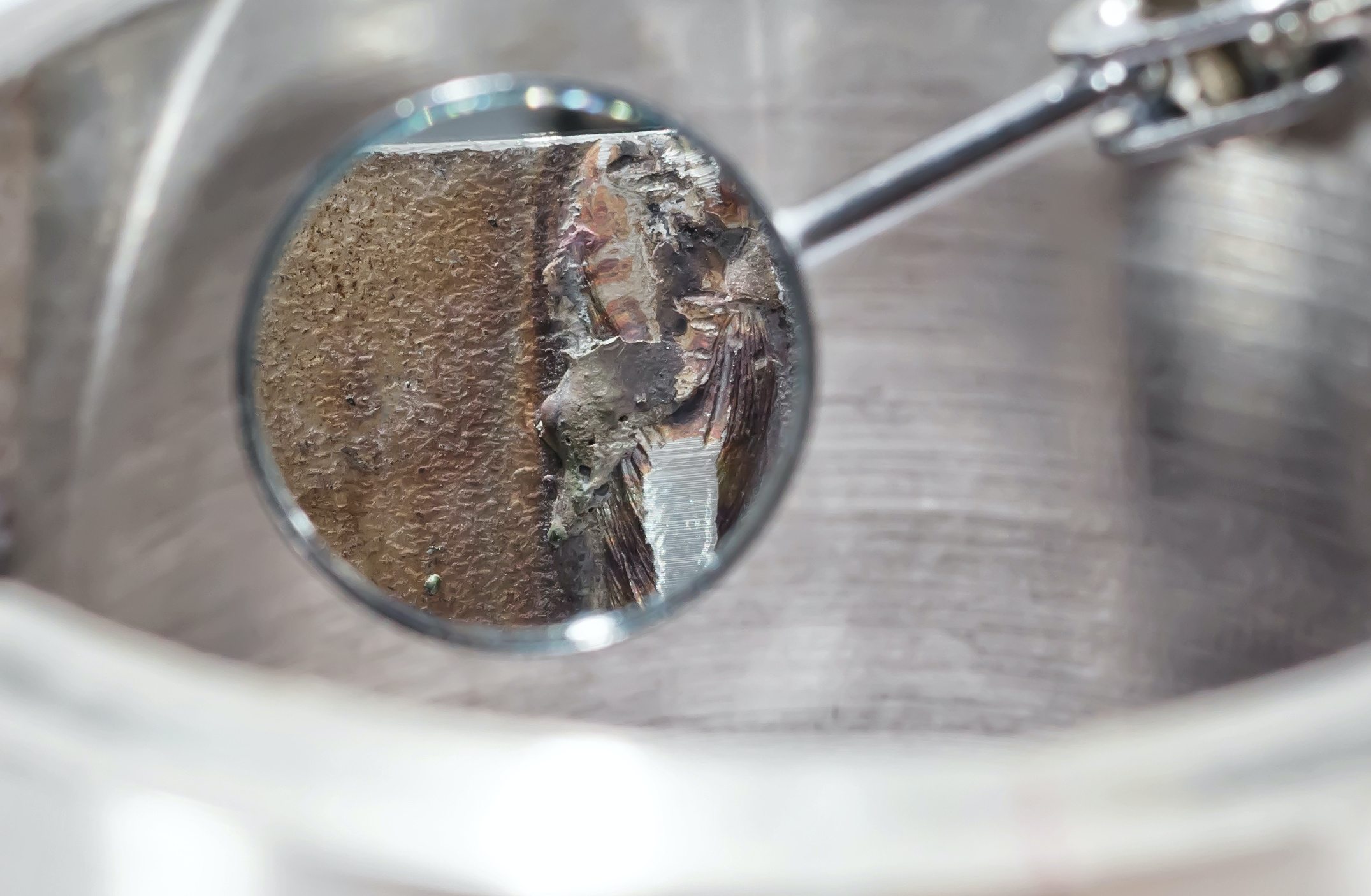
Concept - when paired with automation, you are able to use a voltage on the wire that when the wire is moved to a pre-defined location and a search process is implemented, the wire touches the part in a slow motion to create a short circuit condition.
This short circuit signifies detection of a plane wherein the search is repeated in a different vector to help discern an intersection point. This is repeated at the other end of the weld where two points create a line and the process is set to run from point A to B with placement of the weld.
Advantages - Low cost to implement, easy to implement.
Disadvantages - Cannot adapt to changes in part shape between points, slow process, limited in joint configurations it can be applied to.
Concept - The welding torch is required to have a weave that will oscillate between the two materials to be joined. As the weave moves back and forth in the joint, the system is measuring the inherent voltage in the arc.
As the arc moves closer to one side, the arc length will change essentially creating a change in the voltage threshold, which will induce the weave motion to move in the opposite direction and so on.
Advantages - Ability to keep weld on seam when joint is not repeatable, helps maintain weld quality, reduces weld repair, no extra hardware to pur- chase.
Disadvantages - Needs a minimal material thickness to work properly, not useable for most automotive applications, can increase cycle time.
Concept - System utilizes an external piece of equipment that will implement either a tactile finger which will trail ahead of or behind the welding process feeding back information to another motion control device which is intended to keep the energy in the joint.
In the case of non-arc based applications (i.e. Laser or TIG), the wire itself can be used as a tactile finger.
Advantages - Ability to keep weld/braze on seam when joint is not repeatable, options for tactile fingers are numerous.
Disadvantages - Can be difficult to tune in based on materials / joint configurations used, slip off of finger/wire from joint possible, not always ideal for high speed applications, placement of finger relative to arc not in real time (ahead or behind process).
Concept - Utilizes software features typically integrated into the power source to monitor various key system parameters to determine if they stay within the ranges defined for what are deemed acceptable conditions to ensure a good weld is produced.
Advantages - Low cost, most welding machines have these capabilities built in, locks out process, only authorized personnel can change settings,
real-time monitoring of arc parameters (volts, amps, wfs).
Disadvantages - Reduces but does not eliminate the need for manual inspection, takes qualified personnel to set up alarm windows and to maintain the process.
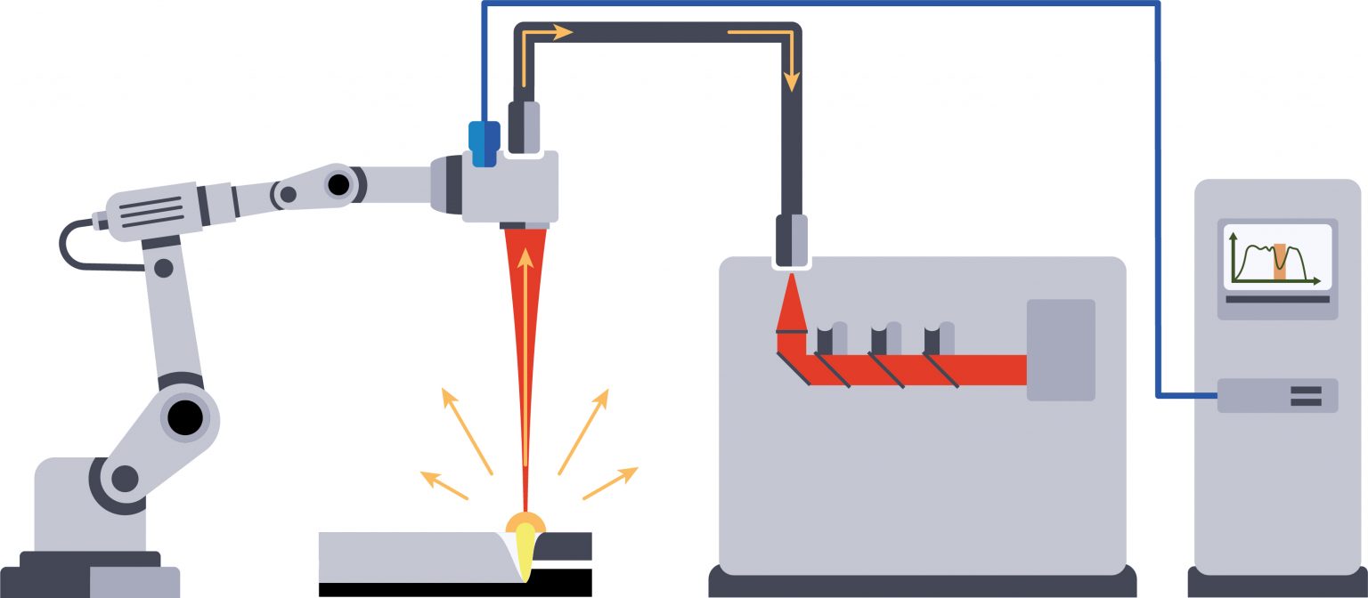
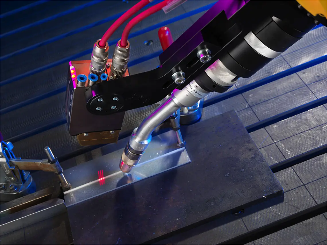
Concept - A sensor is mounted near the torch typically utilizing the concept of laser triangulation to determine the location or gauge the profile of the joint. This information is processed by a controller to determine its relevance and is output to the motion controller (robot, gantry, other) to provide an offset from the planned or taught path to ensure the energy of the process is in the right place at the right time.
Advantages - Ability to keep weld on seam when joint is not repeatable, helps maintain weld quality, reduces weld repair.
Disadvantages - Increases size of torch, limited reach in tight spaces, can increase cycle time.
While the aforementioned technologies will surely help to improve the stability of your processes, one can see that they are not a cure all in the scheme of ensuring good parts are inherently delivered to your customer base.
Taking into consideration there are other means of inspection, we will look at a few of them and how they address certain needs. In the image below, the chart looks to highlight the speed versus reliability of certain inspection processes. Based on the attributes you are inspecting, certain processes will be better than others to detect the defects in question.
It often depends on whether you are simply inspecting for surface based defects as would be the case with the majority of vision based inspection, other methods are able to take a much deeper look into the product and determine issues sub surface such as lack of fusion, porosity, or other inclusions.
With this, we will plan to look at some of the various technologies used in industry today to serve the weld inspection process along with some of their pros and cons.
Concept - Utilizing a cut and etch to ensure weld meets process characteristics.
Advantages - Provides clear indication (at point of cut) the nature of the resulting weld with indications towards penetration depth, throat, leg lengths, etc.
Disadvantages - Destroys the part, small cross-sectional area inspected, results are cut point are not always a sum of the whole. Costly, time consuming.

Concept - Ultrasonic testing technology is a method of detecting discontinuities by directing a high-frequency sound beam through the base plate and weld on a predictable path utilizing high-frequency oscillations (about 20,000 Hz) to propagate into the metal. Waves enter into the tested material and when defects are detected, the signal deviates from its normal propagation.
From the graphical and parametric readings, the nature of the defect can be determined. Both surface and subsurface defects in metals can be detected, located and measured by ultrasonic inspection, including flaws too small to be detected by other methods.
Advantages - Can find defects under weld surface, portable equipment, can be used on many different weld joints, lower cost for equipment, nondestructive testing process.
Disadvantages - Highly dependent on qualified operators who are expensive to employ, expensive training costs, surface defects still require visual inspection, amost impossible to automate, requires secondary process outside of line.

Concept - X-ray is used to determine the internal soundness of welds. Radiography is based on the ability of X-rays and gamma rays to pass through metal and other materials opaque to ordinary light, and produce photographic records of the transmitted radiant energy. X-rays and gamma rays can be used to show anomalies and inclusions within the opaque material as all materials will absorb a known amount of radiant energy.
The fitness of the weld can be determined by inspection of the permanent film record of the internal conditions. The term “X-ray quality“ widely used to indicate high quality in welds, arises from this inspection method.
Advantages - Can find surface defects and sub-surface defects, can be used on many different weld joints, nondestructive testing process, can be automated.
Disadvantages - Highly dependent on qualified operators, high cost of equipment, qualified operators are very expensive to employ, radiation safety concerns, slow process speed cannot be used on 100% of product, only a 2-dimensional picture of the weld and defects.

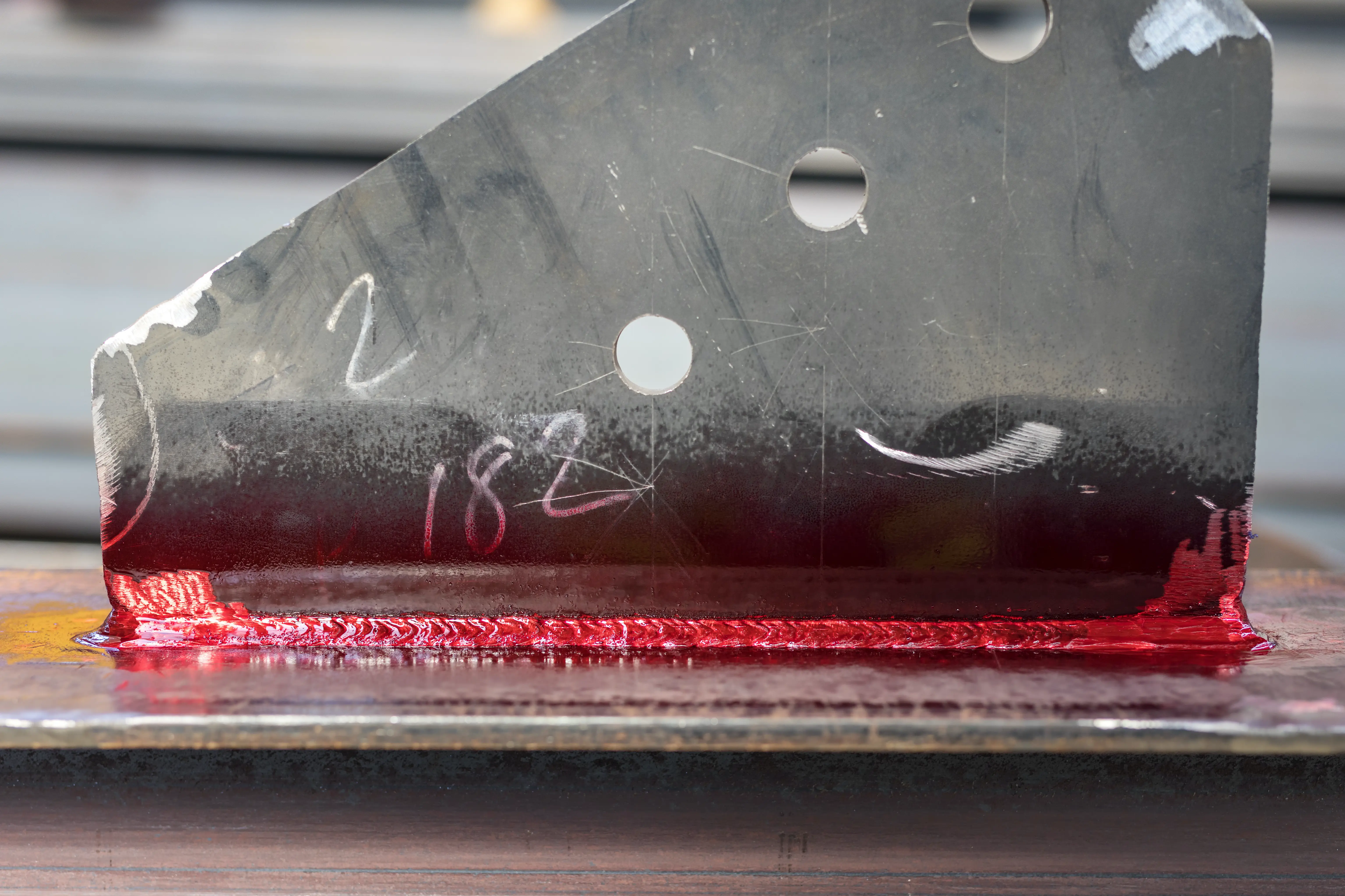
Concept - Surface cracks and pinholes that are not visible to the naked eye can be located by liquid penetrant inspection. Two types of penetrating liquids are used - fluorescent and visible dye. With fluorescent penetrant inspection, a highly fluorescent liquid with good penetrating qualities is applied to the surface of the part to be examined. Capillary action draws the liquid into the surface openings, and the excess is then removed.
A “developer“ is used to draw the penetrant to the surface, and the resulting indication is viewed by ultraviolet (black) light. The high contrast between the fluorescent material and the object makes it possible to detect minute traces of penetrant that indicate surface defects. It is widely used to locate cracks in welds and can be applied to both austenitic steels and nonferrous materials where magnetic particle inspection would be useless.
Advantages - Very easy to find surface defects, portable equipment, can be used on many different weld joints, lower cost for equipment, nondestructive testing process.
Disadvantages - Highly dependent on qualified operators, high training costs, qualified operators are very expensive to employ, requires secondary process outside of line, cannot automate, slow speed cannot perform on 100% of product.
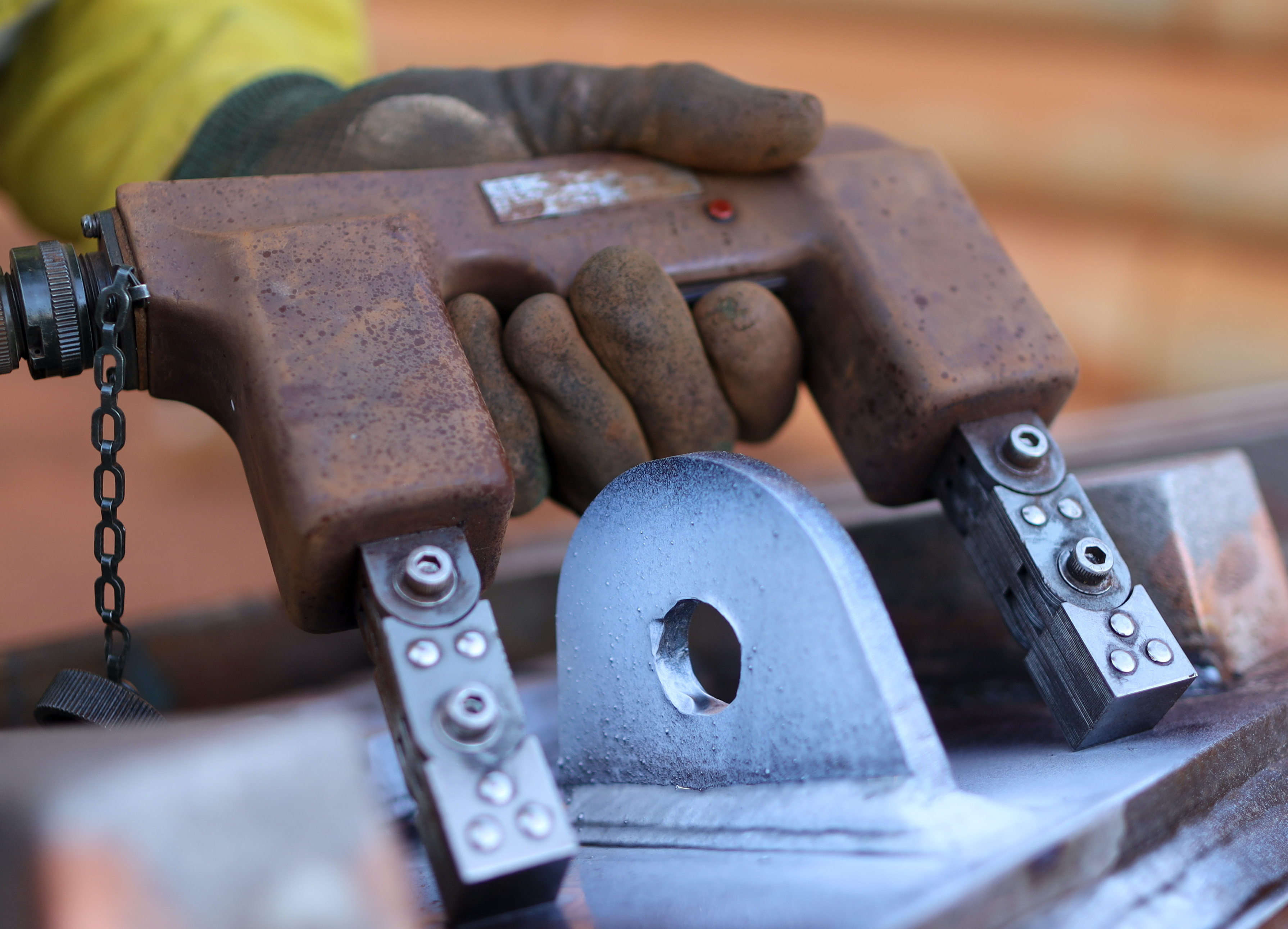
Concept - Magnetic particle inspection is a method of locating and defining discontinuities in welded materials that have magnetic properties. It is excellent for detecting surface defects in welds along with those that are slightly sub surface. In this inspection approach, probes are usually placed on each side of the area to be inspected with a high amperage being passed through the work piece between the probes.
A resulting magnetic flux is produced at right angles to the flow of current. When these lines of force encounter a discontinuity, such as a longitudinal crack, they are diverted and move back through the surface, creating magnetic poles or points of attraction. A magnetic powder is utilized such that when dusted onto the surface, it will cling to the leakage area stronger than elsewhere, thus providing an indication that a discontinuity exists.
Advantages - Magnetic particles can be applied wet or dry, very easy to find surface defects, portable equipment, can be used on many different weld joints, lower cost for equipment, nondestructive testing process.
Disadvantages - Limited to use with ferromagnetic particles, sensitivity decreased with size of defect, highly dependent on qualified operators, high training costs, qualified operators are very expensive to employ, cannot automate, slow speed cannot inspect 100% of product.
Weld Inspection Methods Continued...
For the purpose of further discussion and addressing more high volume, low mix solutions, we will turn our focus to the two remaining methods of inspection – visual and senor based. In sensor based, we will look at 2 particular approaches including vision and laser triangulation based methods.
We need to take a pause here around the topic of manual inspection. For the sake of argument, this needs to be clear...manual inspection should always be the primary method for your weld inspection process. It does not matter what other methods are used as it is one of the soundest methods out there from a reliability standpoint. With proper training, the right people, and laser tight focus, it is without a doubt the best method out there. Therein lies the problem as going back to the topic of imperfect, which is what people are. Even with all of the capacity for mental comprehension that the human brain possesses, manual inspection is not feasible in catching 100% of the defects that occur. This is true often even under 200 – 300% inspections. Simple fact.
Because of this known imperfection, over repair is something that comes into play, as people will tend to the side of caution. From a pure metallurgical viewpoint, this is potentially a worst-case scenario as you can overheat a material to a point of degradation (in steel, perhaps phase transformation which provides a brittle vs. ductile characteristic), which could directly change how it will perform in operation. Over repair also affects your cost base as you use extra materials not needed and spend more labor time than is necessary to produce the part.
With a manually intensive inspection process, the issues of training and retention also come into play. In order to ensure a person is qualified to clearly determine good welds vs bad welds, and do so in an efficient manner, requires considerable effort on the part of the company. Training can take weeks to months to provide an operator all of the skill necessary to do their job at a relatively high level. That, in addition to all of the other aspects the operator needs to be trained in, adds considerable overhead to the organization. It is paramount that not only are the operators trained, but motivated and informed on the importance of their role. Lapses in focus, due to fight with the spouse, money issues, or yesterday’s game along with fatigue that occurs as the days go on are major impediments to a stable inspection process which is very hard for the company to control on a day in, day out basis.
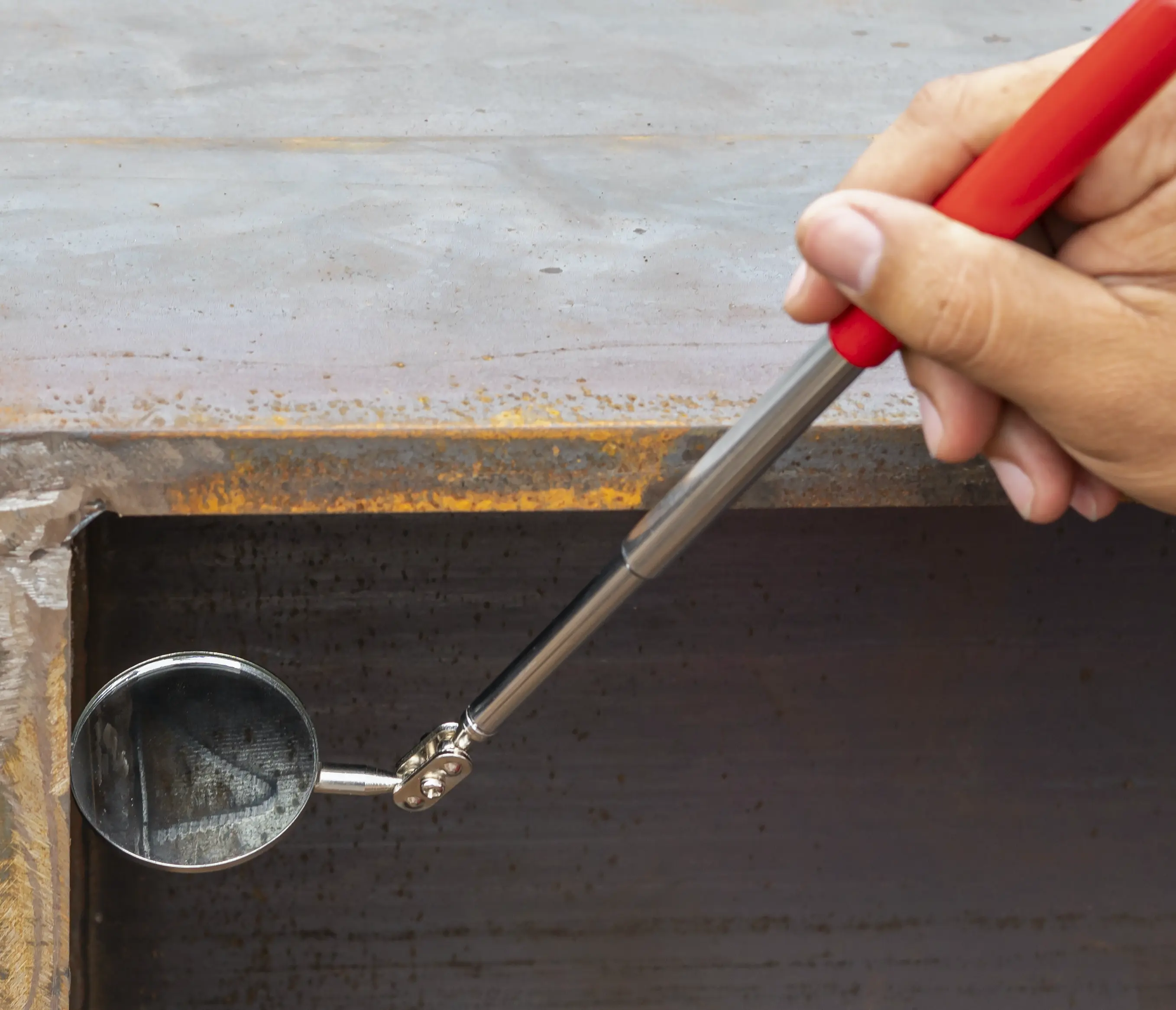
Concept - Visual inspection is often the most cost-effective method and is required throughout the entirety of the welding process - prior to, during and after welding. Many of the written standards require this method be used before any other methods are employed as it proves to be the most suitable method for determining initial fitness of the weld, especially in cases where subsequent, more sophisticated inspection methods are used.
The ANSI/AWS D1.1, Structural Welding Code-Steel, states, "Welds subject to non- destructive examination shall have been found acceptable by visual inspection.“ This method requires little equipment outside of adequate lighting in the area of inspection, good eyesight of the inspector, and likely various inexpensive tools such as a measuring ruler, straight edge, weld size gauge, markers, and other hand tools.
Advantages - Low cost, offers insight to situations where procedures are not followed, correctable, able to be applied in many situations.
Disadvantages - Only suitable for surface defects, loss of attention / focus can result in poor results, no true means of data collection (subjective if so).
Concept - Utilize a sensor-based technology, typically in unison with algorithm-based inspection protocol to visualize a weld in a manner that will allow it to be measured and compared against a known good weld wherein various attributes / anomalies are measured against specifications to determine which facets of the weld meet or don’t meet the stated requirements.
The sensor-based technology will normally be either a vision camera-based approach where pixilation of images are reviewed or via laser triangulation which consists of a diode set emitting light onto a part which reflects to a chip in the sensor that transmits the reflection to an image. The images are then knit together to create a 3D model of the part scanned.
Advantages - High scan speeds, definable limits for process related inspection, provides objective view, robust
Disadvantages - Cost of equipment, technically complex, surface inspection only
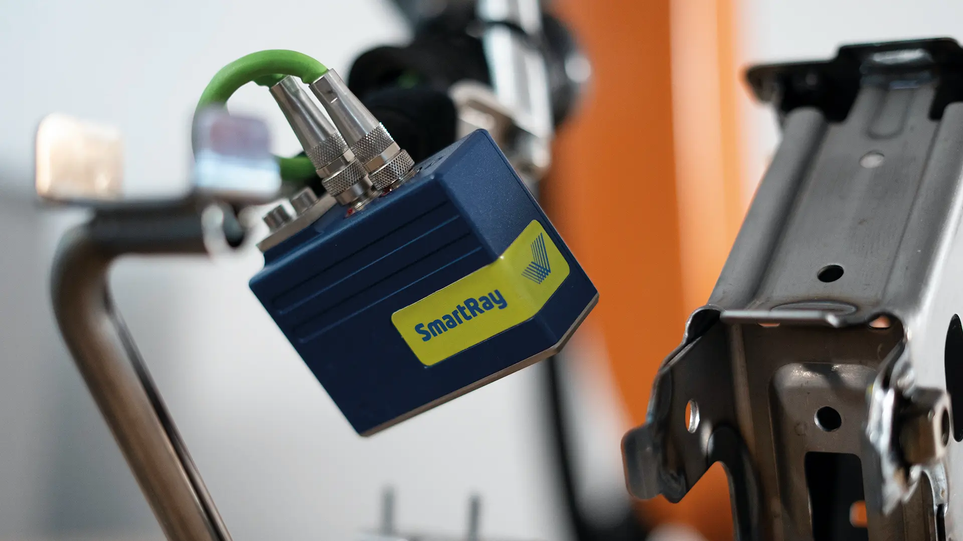
In the case of vision-based applications, the manner in which the application works is tied to the fact that the camera contains a sensor that converts light from the lens into electrical signals. These signals are digitized into an array of values (pixels) and processed by a controller to perform the basis of the inspection process.
There are large volumes of work in and around 3D machine vision and it’s features and benefits as they can provide including anything from machine control to inspection. The intention here is to note that it is a viable solution in this case, however machine vision has its strengths and weaknesses like most technological solutions. Much the same can be said about laser triangulation-based processes as well, which we will turn our attention to.
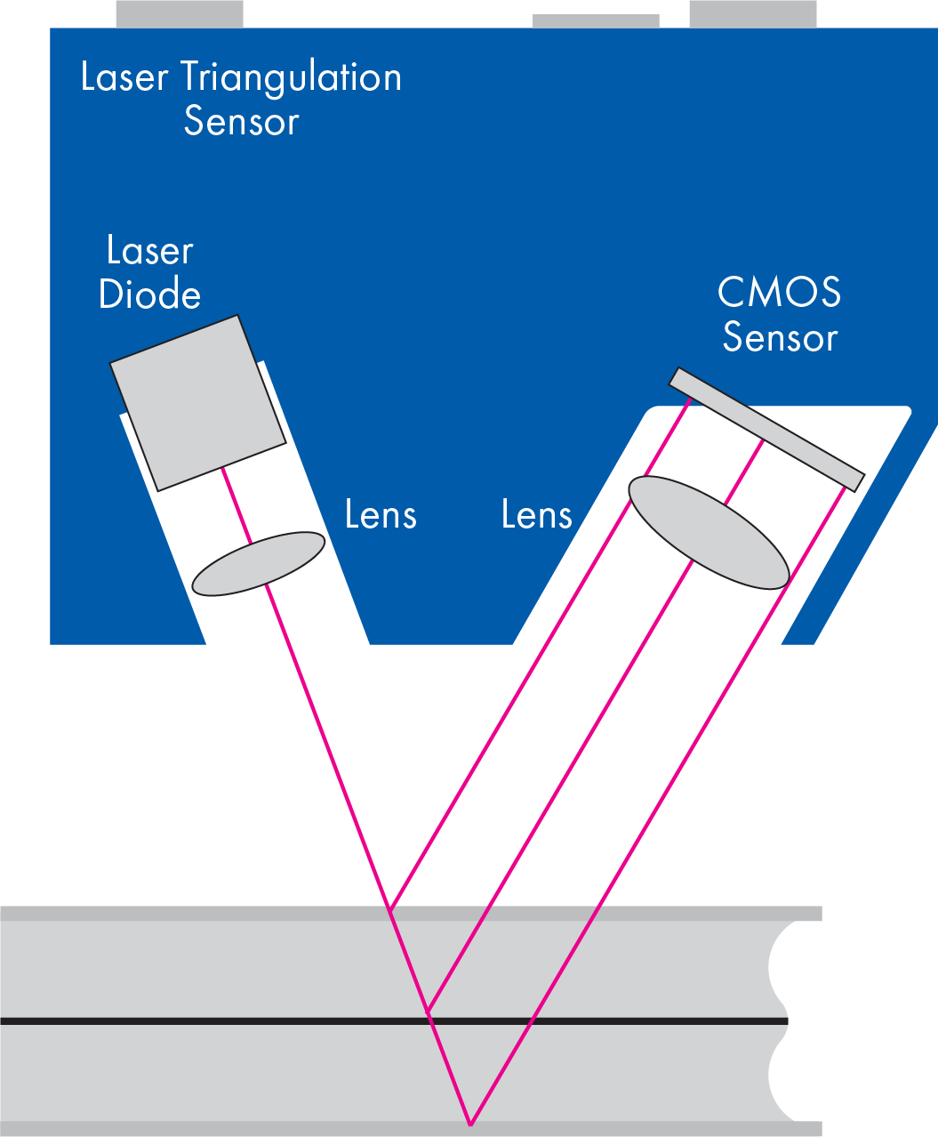
With respect to laser triangulation, it is a method utilized by multiple sensor types as it relates to guidance and inspection processes. The basis of laser triangulation is one based around the concept of reflected and absorbed light.
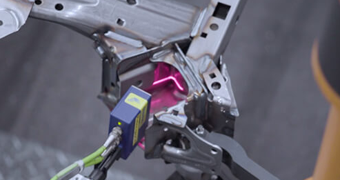
With this process, you have essentially an emitter (diode or other light source) and receiver (CMOS chip) that can take the reflected images of light and correlate them back to a 2D image.
This image is translated into a set of data points based on the calibrated set up of the senor which takes into account its distance from the process, angles of inclination, and speed at which the process is moving. These signals can be streamed and interpreted in real time, as would be the case when using it in an optical seam tracking mode, or the data can be stored and strung together to provide a surface-based model of the items scanned, which is what happens in the case of weld inspection.
In a bit more detail as it pertains to a robotic based process, there is connectivity to other peripheral pieces of equipment such as the sensor controller, robot controller, and manufacturing system’s PLC. The process begins with the sensor controller receiving job and part information from the robot and PLC via fieldbus (Ethernet, Profinet, etc.). The robot in turn moves along the path triggering the sensor in the on condition. The controller in turn receives intensity and profile images from the sensor.
The image is automatically processed and analyzed while being aligned to fit a reference image. From there, a contour model is calculated wherein the weld borders are detected, weld geometry is measured, and defect objects are identified. At this point, items such as weld geometry and detected defect objects are evaluated based on a set of tolerances defined for the weld in question. For every weld, an OK / NOK decision is made and is subsequently sent to the robot and PLC by fieldbus. Decisions for next steps are then taken over by the welding system as to pass on to next station or move to a repair process. In the case of repair being required, the system can be paired with an interactive workstation at the repair location that will guide the operator specifically to the welds in question where they can repair and note in the system that the defective areas are cleanly addressed and OK to move back into the production flow.

With an inspection system, the main components associated with it would be the sensor, its related controller, and a software set that operates on the controller and / or PC based product. There are typically multiple versions of sensors that would be offered from any provider that would best support the needs of the process. Sensors will often vary by key variables such as field of view, standoff, and resolution. The resolution of the sensor will often be a key factor in the size of defect that you are able to pick up in conjunction with the speed of the process. Low resolution plus high travel speed equals picking up big defects only.
So, understanding the limits of what are critical to the performance of your product is essential to know early on in the product selection phase. By not having clear understanding on requirements, you stand the chance of missing defects you do not want or you are unable to meet cycle time due to having to run slower scan speeds than desired. For reference, a standard sensor for inspection of MIG welds will run in the range of 150 – 200 mm/sec, however are capable as well in speeds up to 400 mm/sec and resolutions can go down into the range of single digit microns (μm).
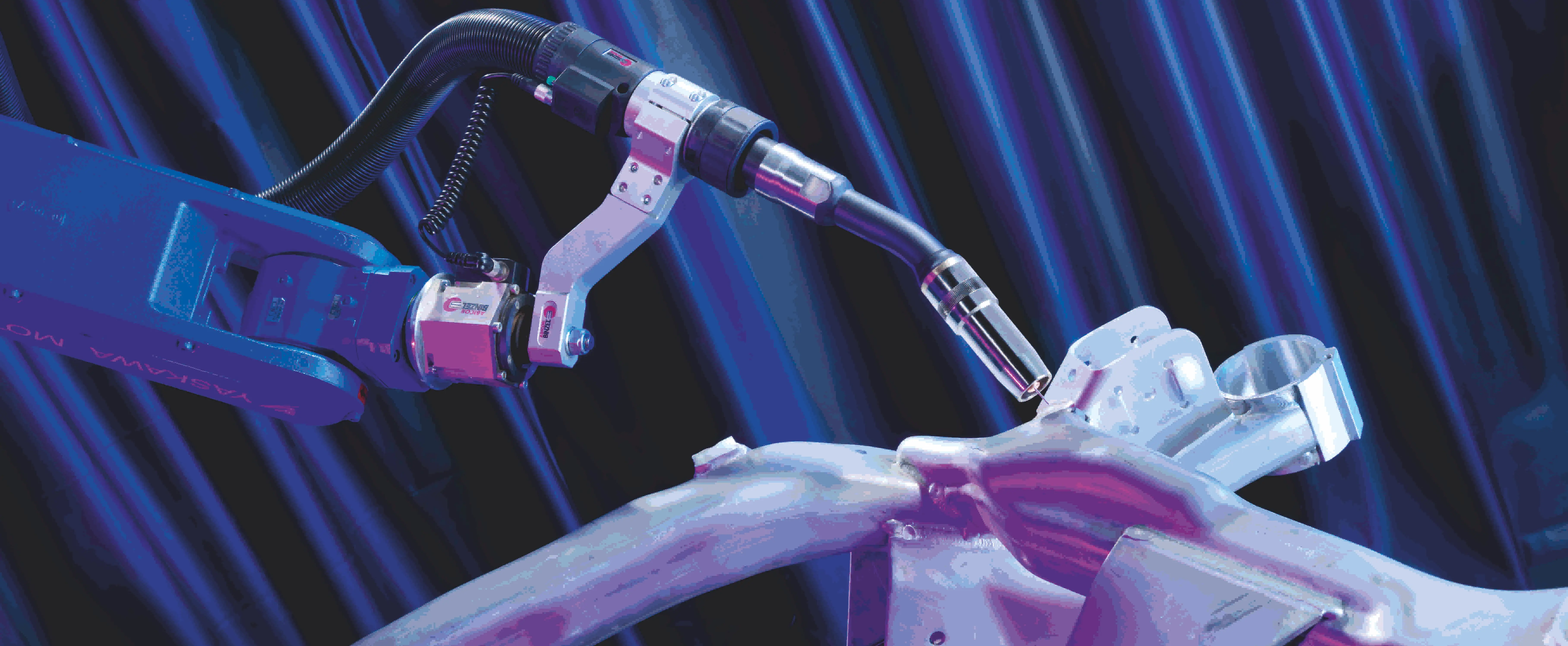
The software associated with the inspection packages are multi-faceted in that you need different tools for different purposes. Software located in the controller is utilized to support translation of data coming from the sensor into a usable form, algorithm-based protocols around setting up of weld boundaries and attribute measurements. There are also communication related aspects of the controller, which helps facilitate data transfer to and from the other system components.
Often, the controller will also provide an embedded PLC to support further transfer of related data. Additional software packages that may be available as well could include:
- PC remote access platform for direct link to controller enabling interface and communication across multiple applications
- Visualization packages utilized at repair stations displaying images of the part being inspected and OK / NOK notifications for each weld. Allows for direct interact at repair station to verify part has been repaired and OK to move on for further processing.
- Data analysis packages that can correlate data around specific welds or parts such that management teams can review and address root cause and corrective actions to improve part operations. Reports could include items such as Pareto charts and other graphical means for displaying data for ease of analysis.
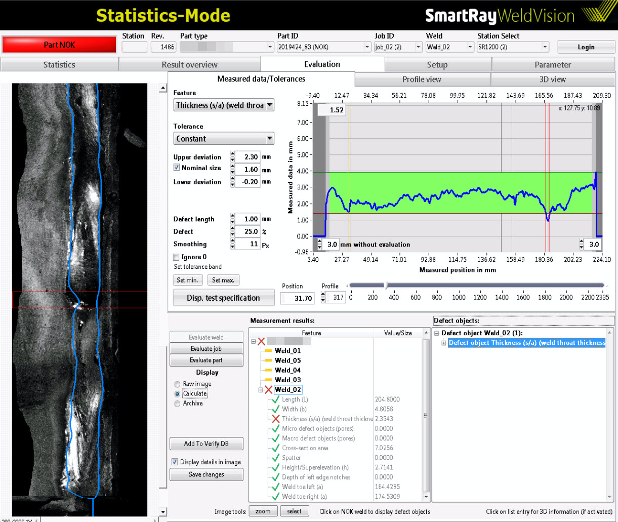
One of the most interesting facets around the sensor-based operation is the ability to take full control of the inspection process. The process, when set up properly, is 99+% accurate providing faster inspection times than human inspection and with the data collection capabilities, it can not only provide historical reference, but guidance as to where your true issues exist. Knowing where to look for improvement is a key benefit, but as the continuous improvement of one’s operation occurs, so does the confidence in the manufacturing process and the boundaries established. In cases such as this, the ability to reduce the quantity of cut, cross section and etch or other related destructive tests could provide both efficiency improvements and significant cost reductions.
The process related to implementing automated inspection is not necessarily a simple one. While it might seem obvious that when you are a producer of parts and inspect thousands to tens of thousands of parts per day, you know exactly what you are looking for. Therein lies one of the main issues is that you think you know what you are looking for, but are you truly inspecting for all facets of all welds ensuring they meet all requirements necessary? When you look at the various attributes being measured and defects being inspected for, it can be a difficult process transitioning to automated weld inspection, as you are needing to take everything that is subjective and objectify it to hard #s that are possible to measure against. Looking at the following, one can see the range of items these systems are capable of checking.
Weld Dimensions
- Length
- Width
- Throat Thickness
- Cross Sectional Area / Volume
- Toe
- Position
- Asymmetry
- Reinforcement
- Distance to Angle
- Overlap Length
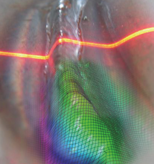
Weld Defects
- Missing Welds
- Incomplete Welds
- Pores
- Skips
- Incompletely Filled Groove
- Undercut
- Spatter
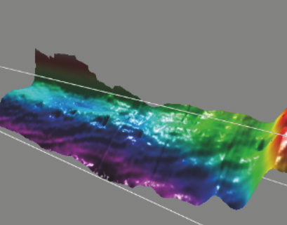
Each of the items noted will require a discrete set of objective characteristics against whicht heinspected parts will be measured. Sounds simple, but in the end, it often comes down to agreement between what the human eye deems as good and what calibrated, analytical values come from the sensor packages. It’s amazing to see a system pick up defects that the human eye is not capable of seeing, as tends to be the case, it will open up your eyes as to how the parts produced are not as good as you think they are.
Sensor-based inspection is suitable as well in addressing inspection across many widely used joining processes. MIG welded parts are likely the most widely applied applications, due in part to their ease of automating and the materials applied to are widespread. This method of inspection is also quite suitable to measure parts produced via TIG, plasma, laser brazing / welding, resistance welding, certain mechanical joining operations along with PVC and glue beads.
As would be recommended in any case, it is best to talk through the options with your preferred vendor to determine the attributes needing inspection and the capabilities of the system itself. Like any type of quality-based system, understanding its repeatability and reproducibility (R&R) relative to the application you are looking for is one of the key steps in determining its fitness for your application.
The next point to address is where this process might best serve your operations. For automated weld inspection to work at its highest level, it is best applied in cases where you have automated processes providing a stable output in a common format. If you have an application where 15 different parts are coming off the same line, the complexity of these applications get cumbersome to manage and maintain. While this technology can work in many different markets, it has an ideal fit within the automotive market due in part to high volume repeatable parts, higher end tooling for consistent placement of parts, and automated welding processes that provide an aesthetic consistency that eases the ability for technology to evaluate.
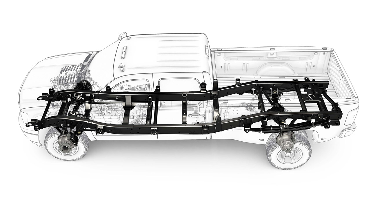
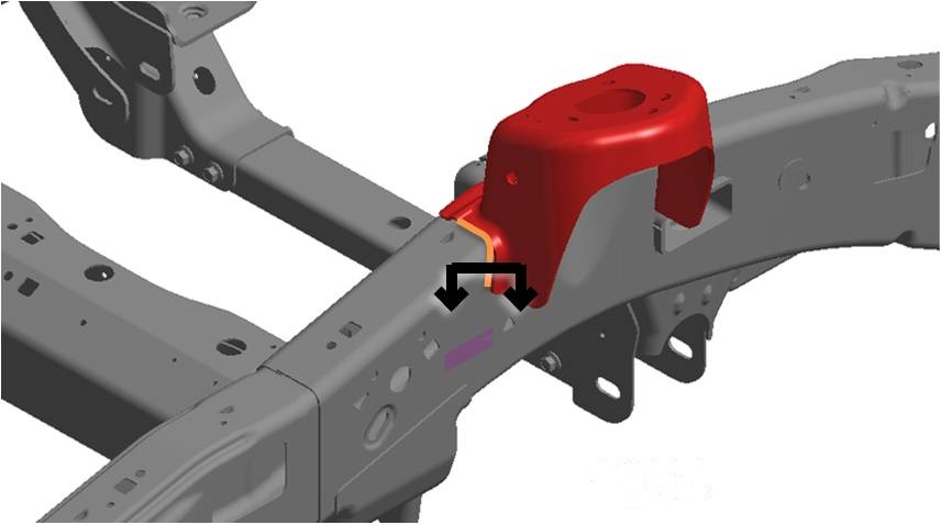
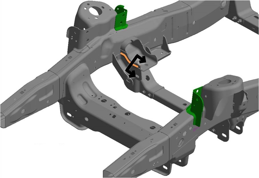
Truck Frames
A perfect application where there are numerous welds that are safety critical in nature and range over a part that is hard to manipulate manually, is heavily automated in its welding, and often possesses close out welds that cannot be inspected unless done at the time they are welded as parts are placed overtop a welded area to complete the build.
Due to the safety critical aspect of the parts, OEMs are beginning to require data records around weld quality for tracking purposes and help ensure the safest and highest quality product for their end customer.
Automating the inspection process will help insure weld quality, provide an opportunity to have less need for destructive testing of welds, lower scrap costs for testing, and possibly provide less post OP repair after the frame has left the production line.
Close Out Welds
As is noted in the above example, product design sometimes creates a need for in process inspection. Certain welds are not able to be accessed at the end of line inspection / repair process
An automated inspection process can eliminate the need for an extra operator station and labor head count. It can also help decrease the cycle time needed for inspection.
Additionally, it can help avoid costly rework or scrap by repairing welds before they are closed out.
Cradle and Structural Parts Inspection
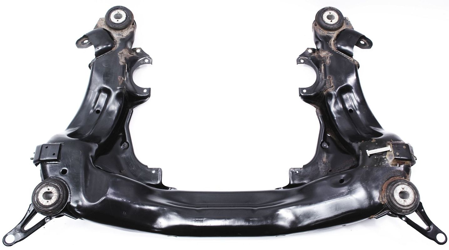
Much the same metrics apply to these as in the first couple of examples. The process is suitable for anything from engine cradles to sub frames to steering components to inner cross members.
Products such as instrument panels (IP’s) fall well into this category due in part to the large number of welds on these assemblies (sometimes in excess of 200 on one part). That, in addition to the short lengths and often safety critical aspects of these parts make it an ideal application for inspection.
The ability to utilize compact sensors along with capabilities to address steel, aluminum, and other materials opens up various possibilities.
Laser Brazed or Welded Parts
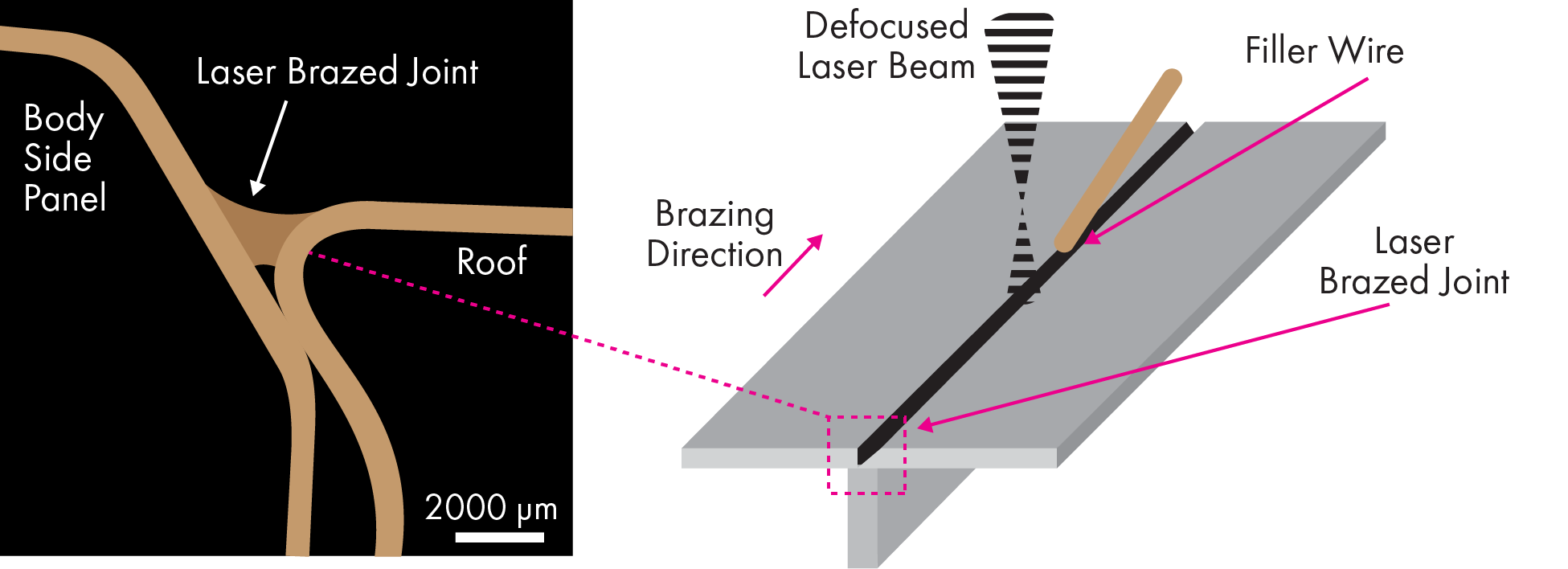
Sensor-based inspection applies to body in white scenarios where the roof pan is laser brazed to the side panels of the vehicle structure.
Sensor-based inspection can apply to various brazed or welded components that fall into the hang on part category such as door, trunk lids, and lift gates. The ability to pick up pores in the 0.1mm (100 um) range, it enhances the ability to catch defects at the process prior to them going to paint, which is often a major directive from the OEMs to go from manufacturing to paint. Catching defects post paint is a labor and cost intensive process because if it even can be repaired, the need to strip paint, repair, and repaint can be cumbersome at best.
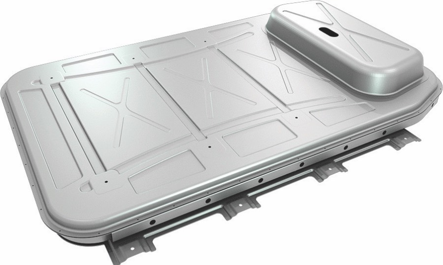
Battery Boxes and EV Related Products
With the majority of all OEMs building electric vehicles, the battery box is a required assembly. The need arises for 100% quality inspection, as these assemblies are extremely difficult to produce and ensure the highest level of safety is present.
They often utilize a combination of laser and MIG based processes for joining and need to be hermetically sealed to ensure components are free from moisture to ensure safety and reliability.
The technology can be applied as well to other segments of the EV product class such as battery cells and welded terminals
Having an automated solution where compact sensors can access tough to reach areas for reliable weld inspection provides a wealth of benefits that can help guarantee quality, provide traceable data, and reduce the chance of quality related issues down the line.
With the application of automated in line weld inspection, there are numerous benefits to the user that can help to greatly increase the efficiency of the operations in areas ranging from accountability to bottom line profitability. Highlighting some of the specific areas of where improvements are made through reduction:
Reduction in physical head count – the total cost per year for a line operator including wages, benefits, etc. in the US starts at $60,000 per year. The resources within the organization focusing on daily inspection can be reallocated within the operation to address other needs.
Reduction in Floorspace – by automating the inspection process, the amount of floor space is typically reduced relative to manual stations. The cost of floor space in manufacturing operations is expensive. Optimizing it for profitable operation is critical.
Reduction of off-line tooling for repair / inspection – depending on the complexity of the part, off line tooling will be required due in part to long repair / inspection times that force them to be done off of the main line. Enables ability to keep repairs on line due to faster, more accurate inspection. Focus is on the bad welds, not all of them. Reduced inspection time leads to more on-line repair time and less need to send assemblies off line for heavy repair. The savings extend as well into logistics as you can reduce the number of fork lift operators needed to support off line repair and less labor itself at the repair process.
Reduction of cut and etch sections – task is time consuming and expensive as- suming the cost per cut is around $8.00. How many cuts are done in a day? For most operations, hundreds. Combining weld parameter monitoring from the power source with weld inspection data showing weld position and surface defect details could provide details that would ensure the process is running under control. Weld development would ensure the welding parameters used would meet cut, cross section and etch requirements. Being able to have real time monitoring of the parameters to ensure they are within the process window and correlate that to an automated weld inspection process-verifying weld is in location relative to the joint and possible surface defects is a powerful boost in ensuring confidence in the process. With the monitoring and traceability in place, perhaps can change daily cuts to weekly or even longer.
Reduction in rework – by having the data built in and around what is good, what is not good, and the frequency that each is what it is, companies can do targeted focus campaigns around reducing rework. By understanding precisely where the problem is, corrective actions can be put in place be it around a stamping die or part of the assembly process leading to variation the process can’t handle. Every inch of repair weld you can eliminate will enhance the efficiency and profitability of the operation.
Reduction in Scrap – there are various ways in which you can reduce scrap with automa- ted inspection such as inspection of close out welds such that you don’t need to cut pieces off to repair a weld that was bad and then covered with another piece. If inspection was in place, the part could have been repaired properly before any other value was added. Cases where major burn through have occurred, but were not caught before other items were added to it or components were misassembled leading to a bad assembly. In line detection can find these defects before the assembly is finished as you don’t need to scrap an entire assembly and a sub component can be kicked out of the line instead of being blindly sent on.
Reduction of risk / liability related to recalls or quality spills – this in turn might be the biggest reduction of all. With the traceability aspect and the data collection capabilities, this can prove to be a business saving move in the end. Application of automated inspection systems in conjunction with good process control enables a much higher chance of ensuring quality product leaves your door, a customer base who trusts that they are getting world class quality, and the long-term prospect of greater ability to garner new work due in part to an enhanced reputation for providing quality parts.

Much of the information provided to this point is related to the concept of how to ensure you have produced a weld that meets all of its intended requirements. This starts with the basis of what is considered to be the pillar of good manufacturing principles – process control and good inspection processes that ensure you meet the requirements of the process due to, or perhaps in spite of, the capabilities of your operation. Make sure you have done the right things to start with by choosing the right process for the job at hand. Ensure that the design is capable of being manufactured and the joint configuration and related tolerances are compatible with the tooling designs and welding processes selected. The proper process parameters are selected, ideally, through a development process, which has identified the window boundaries that ensure when met, good product is produced. Most importantly, you have qualified people assigned to key roles throughout the process to ensure you say what you do and do what you say.
Therein lies the issue when you fail to do what you say. Processes start to deteriorate, resources are diverted to address other more pertinent matters, and technician training suffers due in part to lack of good candidates and underdeveloped pool of workers, and on and on. As with anything in life, it often comes to choosing plan A over plan B which entails an understanding of risk versus benefits and weighing the costs versus rewards the decision may provide. Therein lies the crux of the situation at hand, what is the cost benefit of choosing an automated inspection approach for your critical weldments?
Defects are going to happen as part of a manufacturing process. It is virtually impossible to have a 100% good manufacturing rate thus increasing the importance of having good inspection processes. There are cases as well where a manufacturing process falls out of control and a larger number of defects than normal find their way through the system and get to the customer. Depending on the severity of the defects, it might be a simple quality hold situation where simple sorts are done in house to ensure all parts are evaluated at a higher level and sorted based on whether the parts meet customer requirements.
Events in turn might lead to a continuation of the troubles at hand and lead to larger issues at a customer level such as a major quality event at the customer level where corrective actions are required immediately to get the system under control to a situation where recalls are implemented to address product already in the field.
The main focus as it relates to the inspection process is how to minimize the risk associated with the process. Manual inspection has an effectiveness in the range of 85 to 90%. Adding in 200% and 300% inspection can increase that value to range in the upper to mid 90% range, still not in the 6 sigma range where your catch rate is in the 99%+ range. The low effectiveness is due to a myriad of issues such as fatigue, attention loss, and general human nature.
What are the risks associated with various quality “spills” that get to the end customer? In the case of risks, it might more closely be related to costs. Costs such as the cost of a warranty claim, cost of shutting down the customer, cost of a product recall, and cost of lost trust or future business opportunities due to repeated poor performance.
In order to fully understand the overall impact of the poor performance, let’s look at a scenario of a quality issue and its impact to the operation.
Example Scenario:
ABC Autotek is a producer of widgets. They have been producing widgets as part of a new project for 6 months. Their product launch in the first 6 months has had its ups and downs as it relates to quality of product and on time delivery. As things began to stabilize, they lost of a couple of key people in their operations who took roles with other companies.
A downtime event occurred on one of their widget lines that ate up a fair amount of stock and placed them into a period of strain as they struggled to get the line back up and running. During this time, the attention to detail waned and bad parts started slipping through the net. As a result, the customer started to receive bad assemblies in which the defects were significant enough (and frequent enough) to cause concern from the end user.
As a first response, you place all of your parts in a quality hold situation to allow for additional inspection past that done in process to verify the quality of the parts on hand. Labor is redirected to inspect product at your facility, which will require multiple shifts to complete and roughly 4 people per shift to cleanly address.
Labor is jointly sent to the customer to inspect all parts they have on hand and repair on site what can be repaired so as not to shut down production. From this point you will need to do deep dive into the issue to determine root cause (8D, 5 Why, or other reports that take up additional time and resources) placing additional strain on your engineering, tool and die, and maintenance staff to ensure all facets for corrective actions are covered.
Luckily, being this is a generally non-recurring experience, you are let off lightly from the customer as you were quick to respond, didn’t directly affect production, and they appreciate the effort. Everyone moved past it and went back to status quo.
Then it happens again 3 months later.
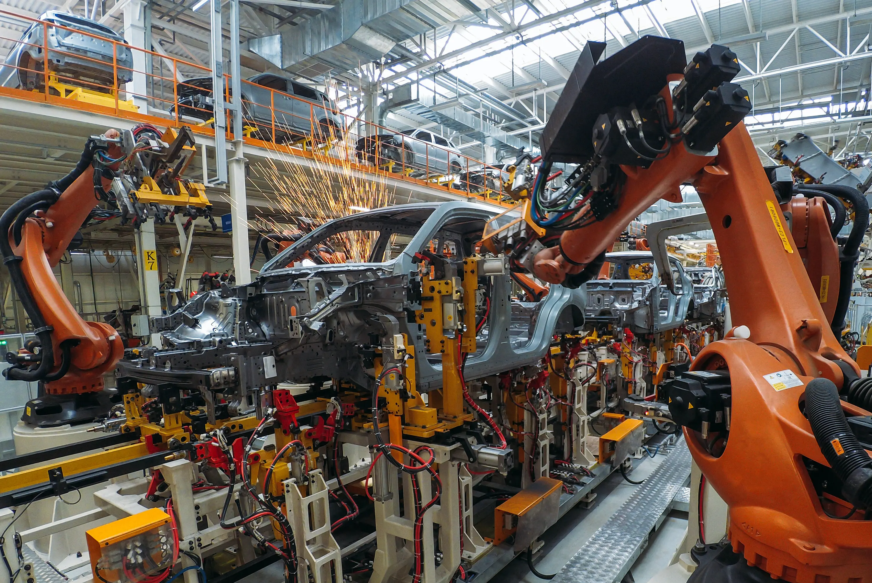
This time, you did affect the production flow of the customer as the defects were now caught on the assembly line at the customer. Rinse and repeat in the sense that you now have staff at the customer doing inspection, staff in house doing 200% / 300% inspection, and additional staff on line to further inspect parts. Being this is a second offense, you are now being requested to bring in outside services to provide 3rd party inspection to ensure no more faulty parts are sent thus disrupting production.
Still making parts at this point, however you are now in a very precarious position as another delivery of bad parts may warrant stronger measures that could (and likely would) impact future business opportunities. To that point, remember that you are now burdened with 3rd party inspectors in house that are not doing this for their health, but at a rather hefty cost that comes directly from your bottom line.
In the case of the first quality spill, you are likely looking at a couple hundred thousand in costs associated with extra staffing, overtime, corrective actions, loss of production, extra floor space consumed by off line repair and inspection. In the case of the second event, you can likely look to add another zero to that cost when all is said and done. To set that point, you can go from getting off light for a couple of hundred thousand to being hit between the eyes with a couple of million.
The topic of recall has not been broached yet either as this will likely add another zero leading to costs in the tens of millions, massive fines, and possible litigation from not only your customer, but the end users of their products. Granted, there are typically contingencies in place to address potential quality issues during the length of a program, but not typically to the point where costs are in the tens to hundreds of millions.
The occurrence of the spills and bad light shining upon your organization due to the inability to control the quality of parts leaving your facility has not only cost a great deal of money as it pertains to parts and resources, but it has also hit your reputation. Your supplier rating has plummeted because of these continued issues, potential for future business had taken a hit, and this poor reputation may spread to other customers in the industry.

With the push to Industry 4.0, customers are requiring more stringent inspection and data recording for easy future reference. With automated systems, you often have the ability to have a centralized repository for parts inspection data, which parts have been repaired in process (traceable as part of the inspection process), and an overall view on outgoing weld quality. Take into account the CQI Standards as part of the North American Auto Industry. The AIAG (Automotive Industry Action Group) is a publisher of the CQI (Continuous Quality Improvement) guidelines. In the case of welding, CQI 15 is in place to address the requirements around the welding of ferrous and non-ferrous metals.
One of the key facets of continuous improvement is data and knowing what to do with it. By utilizing the data attained from the inspection of each weld coming off a production line, the ability to discretely understand where the issues are will quickly enable you to address root cause and implement changes to parts and processes to further increase your first pass quality hit rates.
In addition, this data, along with the ability to reduce RPNs (Risk Priority #s) for your FMEA (Failure Modes Effects Analysis) documents is another key indicator of how to enhance your operations. Taking into account the factors noted within the RPN, they look at:
Occurrence – how many times is it likely for a given defect to occur: ever part to one in a million
Severity – what is the severity of failure should this defect get into service: nuisance to the customer to possible loss of life.
Detection – what is the chance of the defect being detected: every time, sometime, likely never.
The addition of inspection is not going to prevent the defect from occurring, nor will it impact the severity of it when it gets into service, however it greatly increases the chance of it being detected at the point where it is most likely able to be quickly and correctly addressed...at the point of manufacture. When it comes down to automated inspection, it is paramount to have confidence in the system chosen as with any quality-based solution, you are looking to have a high level of repeatability and reproducibility.
It also comes down to choosing the right vendor and integration partner to support you through each step of the process from system design to implementation to post installation support. The confidence achieved often comes from the following:
- Reliability of Output
- Plenty of good sensors on the market to do this. Plenty of good software companies to provide back end support to sensor.
- Lacking is full-scale support around entire process. Choose the right supplier who is capable of providing high-level service.
- User required 99%+ success rate. No “false” negatives.
- Statistics packages which help encapsulate data collection can help guide corrective actions to improve overall operations.
- Ease of Use
- Ability to make changes to algorithms in the field as part conditions change.
- Simplistic troubleshooting of system.
- Exchange of hardware (including calibration / set up) should be able to be done in the field.
- Front Line Support
- Ability to easily get support to your location when not able to address issues internally.
- Remote dial in capabilities.
- Having knowledgeable team behind product capable of providing turn-key support.
With the nature of manufacturing today, especially in the world of welding, the need for inspection has never been more important. Most OEMs are requiring some sort of data based collection around inspection processes to help enhance a higher level of quality in the automotive build process. The requirement of traceability and reducing the risk associated with manual inspection is driving them to push this down into the supply base as a necessary step to secure future business.
We have addressed a number of factors that go into ensuring good parts leave your facility on a day in, day out process. These include areas such as good tooling choices, correct process selection, alternative testing methods, and some of the results of actions when you don’t clearly do what you say you are going to do. The events tied to quality spills can go anywhere from simple contain- ment practice and repair on site to mandated 3rd party inspection to massive recalls.
Automating weld inspection is a small part of the puzzle, but when applied properly, it can help optimize you operations by reducing rework costs. It does so by providing information in support of an optimized process with less scrap, lower repair and inspection costs as you will ideally require fewer repair and inspection staff, less floor space needed, and possibly fewer cut and etch sections due to enhanced process control.
The end result related to the installation of automated weld inspection comes down to providing a level of comfort knowing an objective based solution is applied to a mission critical task. The cost advantages alone warrant further consideration as the very basic points, reduction of headcount, rework, and floor space alone create a viable engine for change. Add in many of the other details noted previously and they create an image of a burgeoning technical evolution that will be a critical piece in ensuring a successful and profitable operation ensuring quality is the answer.
