
Overview & technical applications – How to get perfectly positioned welds in automated welding
Every automated welding process has its own unique challenges. Components are not absolutely identical, positioning during clamping is not always the same and heat from the process can cause material distortion. With manual welding, an experienced welder can compensate this directly without any problems. A welding robot or automatic welding machine needs the "eyes" of a human in a different way in order to recognize the individuality of each component and create the perfect weld seam.
In this e-book, we present different approaches to automated welding in order to produce a perfect weld. You will learn about "seeing" and "thinking" methods, understand their principles and deepen your knowledge of optical seam tracking. You get a direct comparison of optical seam tracking with one line and with three lines. You will learn what makes a good seam tracking sensor and when a corresponding investment is worthwhile for you. A sample calculation illustrates the cost-benefit factor.
Using various practical applications, you will learn about the wide range of possible applications, which in some cases allow completely unexpected additional optimizations.
So if you are thinking about the topic of optical seam tracking, this e-book is just the right introduction for you!
... or scroll down to read the complete guide.
Enjoy!

Norbert Höppe
Head of Business Unit Laser & Sensor Systems
Norbert Höppe has been Head of Business Unit Laser & Sensor Systems at ABICOR BINZEL since the beginning of 2024. He has many years of experience in international sales of products requiring explanation for a wide range of industries, including automotive and rail vehicle construction as well as plant and special machine construction.

Jonathan Moore
Technical Specialist
Jonathan Moore is Technical Specialist at ABICOR BINZEL and has worked with vision-based seam finding and tracking sensors since 1985, when he joined one of the first companies to use laser triangulation vision that was spun-out from the Engineering department at Oxford University. Since then, he has worked covering aspects of the sensor technology design and its use in a wide range of welding applications, ranging in scale from small micro TIG welded parts up to multi torch submerged arc and in industries as varied as automotive, containers, pipelines, power stations, shipyards, submarines and bridges.
What can be done to compensate tolerances?

There are many different tolerances between a joint and a perfect weld. Tolerances in welding include geometric deviations on the workpiece. These are, for example, edge offset, angular tilt, seam volume, gap and seam width, deviations in the center of the joint or inaccurate joint preparation. When welding complex components with many very long weld seams, there is also the thermal distortion of the material. All of this means that the robot's pre-programmed path does not weld the actual joint.
There are 2 basic methods for determining tolerances in the component:
Offline
- Finding the joint without welding
- Saving recorded data
- Calculating offset
- Welding with corrected path
→ This method requires more time because 2 runs are needed. Furthermore, it is not possible to compensate for thermal distortion.
Online
- Joint search with leading sensor
- Data transfer and correction calculation
- Direct adjustment of the robot torch position during welding
→ This method is highly productive and saves costs because only one "search and weld" cycle is required. The welding distortion is also compensated for. This is particularly important for longer weld seams.
There are different approaches to compensate tolerances – and for a perfect weld in automated welding. These are:
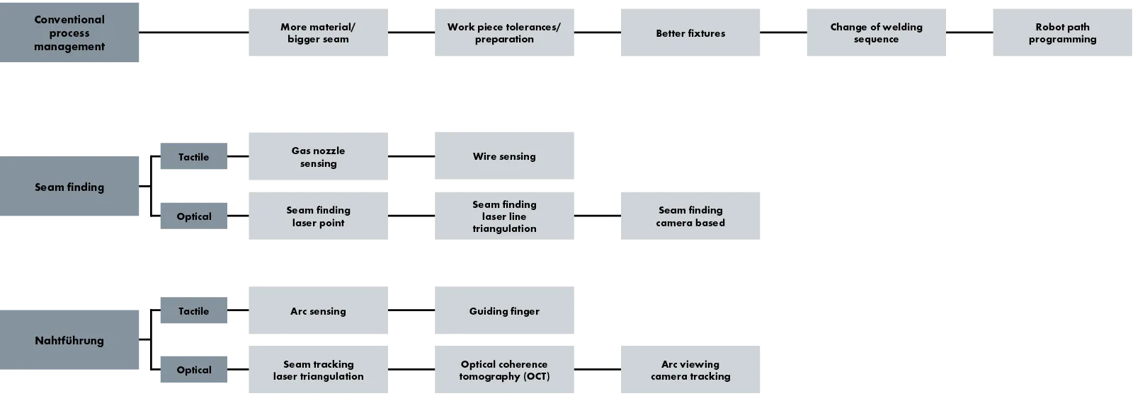
Conventional process management
A widely used method is conventional process management, which does not require any additional tools to localize the joint. This involves, among other things, adding more filler material in the hope that the joint will be sufficiently filled. Better workpiece preparation or optimized clamping devices can also have a positive effect on the weld seam. Sometimes it also helps to change the welding sequence, for example by switching to the other side of the component for the second weld, if required, and thus reducing the heat distortion. You can also keep reprogramming the weld positions whenever your parts vary, to try to compensate for the variation in the position of the seams. This requires regular and ongoing work in the cell, which also increases downtime.
Conventional process management is a standard approach for automated welding systems. However, each of these approaches costs time, requires higher-quality work materials and more expensive tools – and therefore higher costs.
In tactile seam tracking, the robot approaches the component and touches it with the wire. The same principle also works with the gas nozzle. Both are time-consuming because the robot slowly approaches the component until it comes into contact with it and the seam tracking can start. But it is inexpensive. Everything you need for this is available with the system. For this reason, the tactile seam tracking approach is used quite frequently.
There are 3 approaches to optical seam finding:

A relatively simple laser spot scans the surface of the component without touching it. The laser beam must travel at right angles across the surface. This principle works quite well for an overlap joint or fillet weld because the laser can easily recognize the clearly defined edge. The welding robot then receives the information as to where the weld has to start. Although this approach is faster than tactile seam finding, it is still quite slow and not very flexible, but it is inexpensive.

Another non-contact method is distance measurement by means of angle calculation, known as laser triangulation. A semiconductor laser diode projects a laser line onto the workpiece below the sensor head. A camera in the sensor head records the shape or profile reflected by the workpiece surface and can use this to determine the position of the joint.

Camera-based optical seam finding, in which a camera uses an algorithm to identify the position of the joint by means of differences in brightness between the joint and the surrounding material. This principle works well for the pure search for a joint – i. e. before the arc is ignited. However, it is not suitable for seam tracking during welding, as any light is a disruptive factor. In addition, the parameterization of the camera is complex due to different lighting conditions.
There are 2 approaches to tactile seam tracking:
- In arc measurement, the resistance is measured during welding while the welding torch is weaving. Therefore, this is also a very limited application.
- Seam tracking using a guide finger is a very conventional technology which can nowadays only be used with welding machines, but not with robot systems. A guide finger is placed into the joint and the robot torch follows behind it.
There are 3 approaches to optical seam tracking:
Optical seam tracking using laser triangulation is the most flexible and versatile technology that is used in a very wide range of applications. The seam tracking sensor uses a laser and is therefore a very robust technology which is less susceptible to external factors compared to camera-based systems. This method is the fastest way to find a joint and the fastest way to weld it.
One critical aspect of sensor-based seam tracking is accessibility to the weld joint. Some parts can only be reached with the gas nozzle of the welding torch, but not with an attached sensor
Optical coherence tomography (OCT) is a pretty new and also expensive procedure that was originally developed in medical technology to measure the inside of an eye. OCT is mainly used for laser joining.
Arc viewing camera tracking uses a special camera that continuously monitors a weld. The biggest challenge for this camera is that arc welding is subject to many interfering influences such as process lighting. The camera must be able to filter these out while monitoring the arc. Another problem with this system is its lack of flexibility. Due to the wide range of interfering influences, the system must be adapted very precisely to the respective application. One example is the welding of V-seams in pipe welding. In this particular application, it fulfills its purpose well. However, it does not have the same flexibility as a triangulation sensor, which can ignore any interfering light other than the reflections of the laser by means of a filter.
Weld positioning technologies – pros and cons
The following comparison is listed according to the frequency of use of the different approaches in the market. Conventional process management is the most frequently used method. Optical camera-based seam tracking is usually only used for custom-made products.
Conventional process management
|
Upfront investment |
None |
|
Hidden costs – part quality management |
High – e. g. when more expensive raw parts have to be purchased |
|
Hidden costs – jigging and workpiece positioning |
High – e. g. when higher quality clamping devices have to be used |
|
Hidden costs – over welding |
Yes – more material (weld wire, gas) and lower welding speed required |
|
Hidden costs – part reprogramming |
High – may require the robot path to be adjusted frequently |
|
Quality |
Low – e. g. part reprogramming is reactive – done after bad parts are produced |
Technically supported methods
Seam finding
| Costs | Weld length |
Measurement |
Seam type |
Adaptive |
Comment |
|
Tactile, with wire or nozzle touch |
|||||
|
Very low cost of use – hardware usually already included but requires reprogramming |
Only applicable to short welds – cannot be used for tracking |
Several seconds long to scan wire over part |
Limited – requires a large (min. 2–3 mm) feature to detect reliably |
None – does not measure seam geometry (e. g. gap or mismatch) |
Most commonly used |
|
Optical, with laser line sensor (laser triangulation) |
|||||
|
High – investment costs for sensor system and installation work |
Good for short welds like for example tack welds |
Fast – side and height measurement in under 1 second |
Very flexible – wide range of seam types |
Yes, available depending on seam type |
Most flexible |
|
Optical, with laser spot sensor |
|||||
|
Not very high hardware costs compared to laser line sensor but investment costs for software and installation |
Only applicable to short welds – cannot be used for tracking |
Slow – but faster than wire sensing |
Less flexible than laser line – requires well defined edge or feature |
Limited |
Not widely used |
|
Optical, with area camera |
|||||
|
High – investment costs for sensor system and installation work |
Good for short or longer welds but not tracking long seams |
Relatively fast for side measurement |
Requires contrast to detect seam and features |
None |
Sensitive to ambient lighting and part surface finish. Rarely used – mostly replaced by laser line sensors |
Seam tracking
| Costs | Weld length |
Measurement |
Seam type |
Adaptive |
Comment |
|
Tactile, through arc tracking |
|||||
|
Very low cost of use – hardware usually already included but requires reprogramming |
For long weld seams, okay for tracking |
Seam finding slow (uses wire sensing) and requires weaving so slow welding |
Requires thicker material as lap or fillet weld |
None |
Requires weaving movement so slower welds on thicker material and more welding consumables |
|
Optical, laser triangulation |
|||||
|
High – investment costs for sensor system and installation work |
For short and long weld seams, okay for tracking |
Seam finding fast and can weld at full process speed |
Applicable for many seam types |
Yes, as appropriate for seam type |
Most flexible |
| Optical, OCT | |||||
|
High – specialized approach for some laser welding applications |
For short and long weld seams, also for tracking |
Fast |
Lap joints (laser) |
Limited, depending on the application |
Rarely used, expensive technology, sometimes used in laser welding |
|
Optical, arc viewer camera tracking |
|||||
|
High – specialized approach for some welding applications |
For long weld seams, also for tracking |
Fast |
Limited – currently only for specific machine and seam types |
Limited, depending on the application |
Rarely used, expensive and specific to a few welding applications only |
Direct cost comparison of these methods
|
Accuracy |
Speed |
Hardware |
Production cost per part |
Accessibility |
Process |
||
|
Toleranz-Management |
Bigger seam |
–– |
– |
€ |
€€ |
++ | ++ |
|
Work piece tolerance |
–– |
n/a |
€ |
€€€ |
++ | ++ | |
|
Fixtures |
–– |
n/a |
€€ |
€ |
++ | ++ | |
|
Change in welding sequence |
–– |
n/a |
€€ | € | ++ | ++ | |
|
Nahtsuche taktil |
Gas nozzle sensing |
– | –– | € | €€ | ++ | –– |
|
Wire sensing |
o |
–– | € | €€ | ++ | –– | |
|
Fronius Wire Sense |
+ | o | €€€ | € | + | –– | |
|
Nahtsuche optisch |
Laser point |
+ | o | €€ | €€ | o | ++ |
|
Laser triangulation |
++ | + | €€€ | € | – | ++ | |
| Camera | + | + | €€ | €€ | – | ++ | |
|
Nahtführung taktil |
Arc sensing |
+ | –– | € | € | ++ | –– |
|
Guiding finger |
o | + | € | € | – | o | |
|
Nahtführung optisch |
Laser triangulation |
+++ | ++ | €€€ | € | –– | ++ |
| OCT | +++ | ++ | €€€€ | € | o | –– | |
|
Intelligent arc viewing |
+ | ++ | €€€ | € | –– | – | |
o = balanced + = good – = bad € = costs n/a = not specified
Conclusion of the comparison
Apart from OCT – which a pretty expensive method – there is only one technology that is flexible enough to be used in a wide variety of applications: laser triangulation.
Optical seam tracking is the only method that enables targeted processing even in the event of dynamic deformation of a component due to process heat. This method also compensates any deviation between the actual component and the programmed waypoints.
There is no universal solution for "the one and only seam tracking" for the perfect weld. Every challenge is individual. However, optical seam tracking with laser triangulation offers the best combination of robustness, flexibility and speed.
3 x optical seam tracking in practice
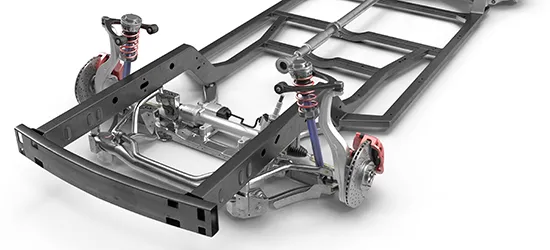
A Tier 1 supplier saves up to 50 % filler wire in his production step when welding a 500 kg pickup truck frame. As the seam is now precisely positioned, thinner and also less filler wire can be used.
In a production line with 2 x 8 robots for the welding of a structural body part (B-pillar), 2 manual rework stations could be saved.
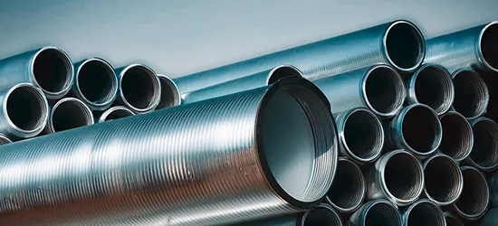
A manufacturer of stainless steel tubes had amortized his investment in an optical seam tracking sensor after just 3 months because he was able to significantly reduce his reject rate.
Principal of optical seam tracking
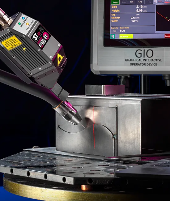
Optical seam tracking is used to recognize the joint to be welded and to follow its actual course. The sensors used for this have adaptive control. This means that they detect geometric deviations such as edge offset, gap width, seam width and seam volume and pass this information on to the system, which in turn directly adjusts the welding parameters. The seam properties are recorded using laser triangulation (light section method), transmitted to the guide machine and adjustments are made almost in real time.
If you want to use an optical system, it is important that the joint has clear geometric features. These features must be aligned within the view of the sensor. Any feature, such as a butt joint must have a gap or mismatch (hilo) greater than the resolution of the sensor. A square edge butt joint with a very small feature is a challenge for an optical seam tracking system, but can often be worked with if the joint has a small break or radius on one edge.
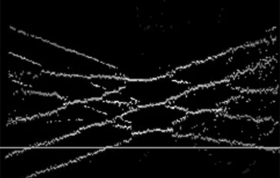
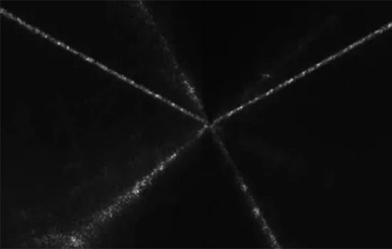
Contamination or damage to the workpiece surface may lead to measurement inaccuracies. The same happens with highly reflective surfaces that resemble a mirror. More on this coming up.
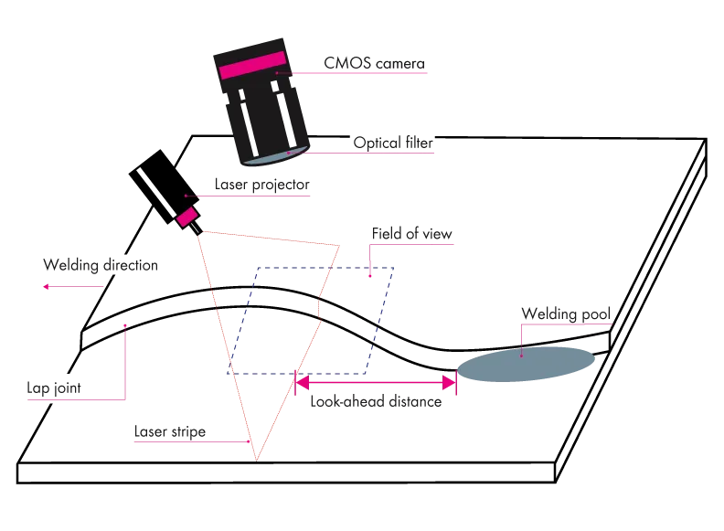
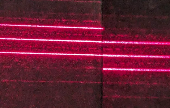
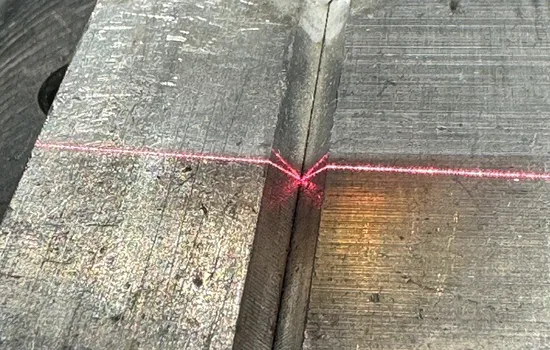
Laser triangulation is a process for detecting, measuring and analyzing the surface of a workpiece. A laser projector in the sensor head projects a laser line, usually red, onto the workpiece. The light of the laser line is reflected by the surface of the component. The CMOS camera – Complementary Metal Oxide Semiconductor – in the sensor head records the reflected light. This camera is arranged to view the laser line from a special angle (triangulation angle) and records its shape and position. Depending on the distance between the sensor head and the workpiece surface, the reflection arrives at a different position in the camera image. The position and shape of the laser line are measured and analyzed in the camera image using algorithms in the sensor. This information is transmitted to the robot controller or welding machine and used to control it.
If necessary, the welding path of the robot torch is corrected. The great advantage of this is that the measurement is continuous. This makes laser triangulation very suitable for use for tracking all the way along the seam.
Laser triangulation can be used on all materials such as structural steel, stainless steel, aluminum, titanium, copper and brass, and even on non-metallic materials such as plastic and the like. However, it depends on their reflection behavior. Problems only arise with very highly polished surfaces that resemble a mirror. The reflections then scatter so much that the camera is no longer able to clearly distinguish what it is seeing.
The sensor must be setup correctly, starting with a good mounting position so it can see the seam clearly and then telling the sensor where it needs to track to produce the perfect weld. We will go into a little more detail below.
Mounting the sensor
The first step is to mount the sensor in front of the welding torch. The position of the sensor must be chosen so that:
- the sensor can see the seam clearly
- the sensor is measuring just in front of the welding torch, so it can measure the actual position of the seam just before it is welded
Setting the parameters
For each weld the sensor is to track, the sensor needs to be set up so that it knows what to measure and what the joint is expected to look like.
For the joint:
- Settings to optimize the sensors view of the surface
- Shape of joint (joint type, angles, curves, bends, etc.)
- Where the welding wire should be positioned
The robot controller
As for all robot welding systems, the robot controller needs to have an accurate Tool Center Point (TCP). When using an optical seam tracking sensor, the robot controller also needs to know the mounting position of the sensor in front of the welding torch. This is done by a special sensor calibration routine in the robot controller and a calibration plate. The robot moves the sensor over the calibration plate and uses the sensor measurements to calculate precisely where the sensor is mounted relative to the welding torch.
Transferring the data
The sensor and robot controller talk to each other using an Ethernet connection using the TCP/IP protocol. The robot controller tells the sensor when to make measurements and which joint is about to be welded. The sensor then sends to the robot controller the position of the seam under the sensor, as well as additional information on the geometry of the seam. The robot controller uses the measurements of the seam position from the sensor to calculate the correct path over the seam to produce a good quality weld. It can also use the geometric information to adapt the welding process, if required.
Challenge: look ahead distance and field of vision
Online seam tracking systems work with a look ahead (preview) distance between the sensor measurement and the welding torch. The sensor look ahead distance is necessary in order to:
a) give the robot reaction time for path correction and
b) to avoid looking directly into the weld pool and welding arc.
The challenge here is that the look ahead distance must not be too long so that the measurement can take place as close as possible to the TCP. There also has to be enough time to process the measured data. For certain welding processes, such as submerged arc welding and processes with additional wire feed (TIG with wire feed) the sensor is usually mounted further away from the welding point to be clear of the flux or wire feed.
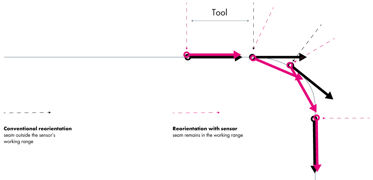
However, it is important that the joint remains within the sensor's field of view. Depending on the bend of the joint, this can be more challenging. The programmed robot positions must ensure that the sensor has a good view of the seam at all times.
Precise measurement, precise guidance
In addition to other points, the following 3 criteria are particularly important for optical seam tracking:
- Accessibiliy
- Resolution
- Field of view
Depending on the nature of the component, a structure can sometimes be complex and therefore a problem for the entire technology. With complex components, for example, accessibility to certain seams can be severely restricted.
There is a conflict between field of view and resolution if the camera parameters remain unchanged. This means that the larger the field of view, the lower the resolution – and vice versa. Various models of sensor are available to allow the optimal balance of field of view and resolution depending on your application.
Optical seam tracking to the point
Inadequately prepared and poorly clamped components are common sources of error in robot welding or automated welding. The optical seam tracking is the eye of the robot. Using laser triangulation, the welding robot or automatic welding machine receives information about the joint to be welded. A good seam tracking sensor detects deviations in the seam position and adjusts the torch path in real time. Optical seam tracking is therefore a reliable method for locating the joint to be welded and reliably guiding a welding torch or laser welding optics..
In automated MIG/MAG welding, TIG welding and laser welding, such intelligent torch guidance can significantly reduce rejects and rework.
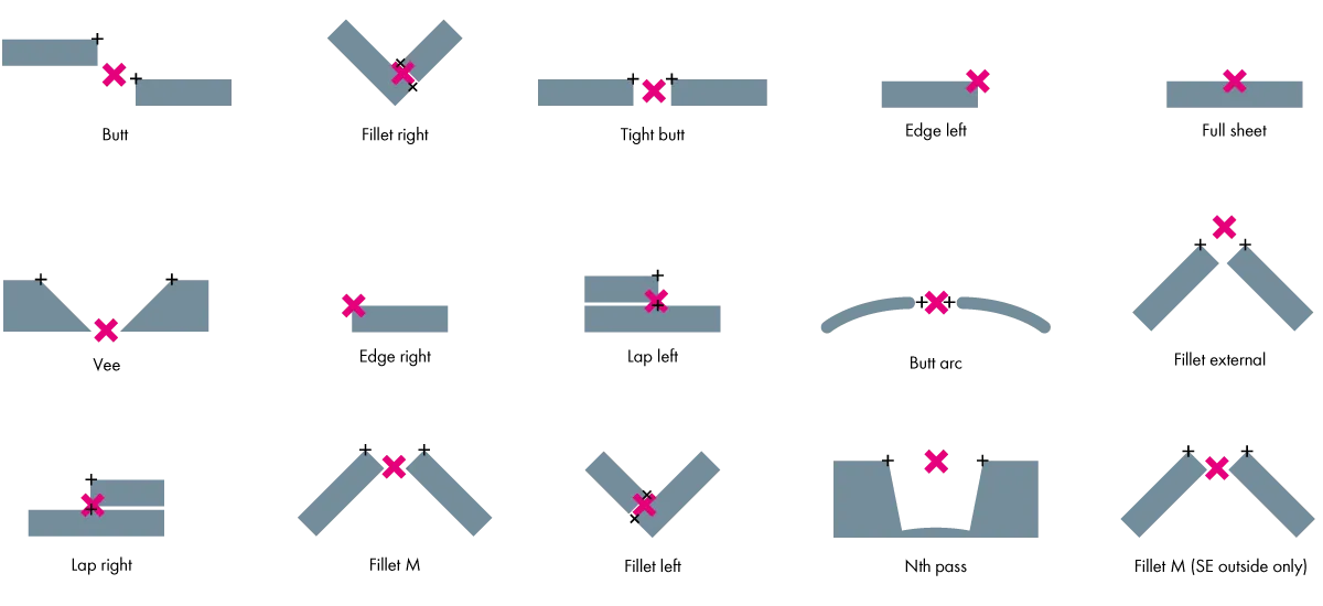
For the following joint types, a good optical seam tracking sensor creates the perfect weld – with the left and center rows representing standard joint types and the right row showing special cases:
Optical seam tracking sensors come with 3 lines and 1 line.
Three lines vs. one line – a comparison
We are often confronted with the question of which principle is better for optical seam tracking: laser triangulation with one line or with three lines. Our first response is: "It depends on the application for which you need the sensor". In the following, we would like to compare both approaches and explain the advantages and disadvantages.
The main arguments for three lines are:
- It allows the sensor to make additional measurements, such as orientation of the part to the seam
→ Fact is: It is not possible to send sensor data to the robot using any of the standard robot interfaces, such as those from ABB, Fanuc, KUKA, Yaskawa, etc. The welding robots cannot use these additional information at all. This means that the robot is not able to use any additional information.
- The measurements are faster with 3 measurements per image than with one measurement per image
→ Fact is: Most robot interfaces can only transmit approx. 15–20 measurements per second to the robot controller. So even with 1 line the sensors are already faster than most robot controller can accept measurements.
- With 3 measurements per image there is a high degree of reliability with regard to the correctness of the measurements
→ That means: Having 3 measurements in each picture means that these 3 measurements can be checked against each other to ensure that they are selfconsistent
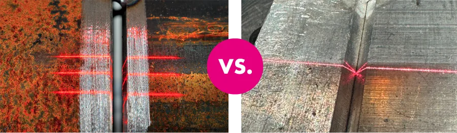
→ Fact is: Software with 1 line compares every measurement with previous measurements and makes sure that they are within acceptable limits. Very good sensors with 1 laser line even have the ability to specifically check for regions with tacks and block any incorrect measurement when detecting a tack.
The following table contains a detailed analysis of the most important differences between a 1-line sensor such as the iST ARC seam tracking sensor from ABICOR BINZEL and a 3-line sensor.
|
Lap joint |
Comments | 1-line sensor | 3-line sensor | Advantage |
|
If the gap varies then the 3 line sensor measurement can fail on certain combinations of metal thickness and gap. |
No disadvantages |
If the size of the overlap joint (metal thickness + gap) is close to the distance between the laser lines, the laser lines are aligned for 2 of the lines. Guiding error! |
1 linie | |
| Fillet joint |
A shiny fillet seam causes reflections of the lines for all laser sensors. |
With only 1 line, there is only 1 set of reflections to process. This simpler image means that measuring the joint position is more reliable. |
With 3 lines there are three sets of reflections that overlap each other, creating a much more complex image and more failed measurements. |
1 linie |
| Butt joint |
Consideration: Doesn’t 3 lines make the measurement on butt joints more reliable? |
Good 1-line sensors have software filters between multiple images to filter out any incorrect measurements and specifically to check if the sensor is over a tack. |
Consistency check of 3 lines within an image. No filtering between the images. |
3 lines for very tight butt joints |
| V-joint/U-joint |
The sides of the V look like a fillet weld and often have reflections |
Same advantages as a fillet weld. The software looks for the top (parent) surfaces and sides of the V-groove to give accurate positions for the top corners, width, mismatch and root. |
Potential problems if the depth of V-groove aligns reflections with the line spacing, causing the lines to overlap and measurement errors/failed measurements (similar to lap joint) and with reflections in the V-groove. |
1 linie |
|
Finding/measuring on small diameter parts |
It’s easier and clearer to see where you are measuring with a single line. |
Possible, as long as the part is large enough to reliably place the laser line on the feature. |
All 3 lines must reliably be on the feature to be measured – so there must be a larger area for the sensor to look at. Harder with smaller parts. |
1 linie |
|
High speed (laser) welding |
Both sensors can make measurements faster than the robot interface can process them. |
One measurement per frame. 30–80 measurements/sec. Used to track at up to 6 m/min. |
50 measurements/sec. Higher measurement speed only usable with special machines. |
3 lines only for high speed special machines. |
Typical questions for comparison
Why do sensors with 3 lines exist?
These sensors were developed primarily for applications where speed is the main focus. Here, sensors with 3 or 5 lines can have advantages.
Did the developers of sensors with 1 line develop this type of sensor because it is easier?
No, a 1-line sensor is the better choice for general welding applications.
3 lines give more information about the seam orientation.
In principle, that’s correct. However, the interface between sensors and the standard industrial robots like ABB, Fanuc, KUKA, Yaskawa, etc. for seam tracking don’t let you make use of this information.
Measuring is faster with 3 lines.
With 3 lines you can potentially make 3 measurements with every camera picture. However, most robot controllers can only process 15–20 measurements per second. Two additional lines such as those of a 3-line sensor can therefore not be processed by the robot controller. Since both a 1-line sensor and a 3-line sensor work with more than 30 measurements per second, a faster measurement brings hardly any advantages.
Having 3 lines gives you redundancy in your measurements.
With 3 lines and so 3 measurements in each image, you can check whether the measurements are consistent before they are transmitted to the robot controller. But: Good 1-line sensors have a software filter that checks whether the measurements are consistent with previous measurements and uses this to filter out any inconsistent measurements. Some sensors also have a specific software filter to help stop spurious measurements when going over tack welds.
Needing all 3 lines over the seam means that using the sensor to measure the position of smaller features is not reliable. You have to have all 3 lines on the part to get a measurement at all. If the scan runs over a tacking, there is no seam tracking at this point. Since all 3 lines are also needed to detect the start and end of the joint when measuring with a 3-line sensor, this does not work as expected in some control systems.
Conclusion
Many of the perceived advantages of 3 lines are not advantages in practice with robot arc welding. Additional functions in the sensor software make these perceived advantages redundant. Nearly all sensor manufacturers agree that the advantages of a single line outweight the advantages of 3 lines.
What makes a good seam tracking sensor?

The perfect weld seam in automated welding and robot welding is only possible if the robot knows where to weld. The basic requirement for this is a good seam tracking sensor. This should ideally have the following properties:
- precise
- reliable
- flexible
- easy to use
Placing the weld seam where it is needed saves money. Often a lot of additional material is used with the welding process in the hope that the robot will "hit" the joint to be welded and fill it.
Creating the perfect weld, even when the heat is on. This requires reliable technology in tough environmental conditions. A good seam tracking sensor can be gas cooled and liquid cooled. If required, an optional cooling device can reduce the temperature of the cooling air and so improve cooling.
Good seam tracking sensors can be used for a wide range of applications. This helps, for example, if you are a system integrator. You then do not have to learn different sensor technologies in order to put together the right technology for your customer. One sensor type with reliable technology is enough. This is flexible enough to even cover special applications with one and the same sensor type. For customer-specific requirements, you need no additional sensor that is only suitable for this requirement.
It's all about finding the right balance between ease of use and the flexibility to get the right parameters for the individual application. Too many parameters can quickly become overwhelming. A good seam tracking sensor provides these, of course, but only by displaying the information required for the task at hand. "Guidance" makes operation more intuitive, and no additional long-lasting application training is required.
Good sensors are not only easy to use but can also be used flexibly for different applications.This gives you the option of welding a different component in the same welding cell, for which you only need to adjust a few seam parameters.
Often crucial: service & support
Service & support should always be provided when purchasing a seam tracking sensor. After all, the best sensor is useless if during installation questions come up and these are not answered. Especially if you are an integrator and usually have to deal with your customers' very specific applications, the manufacturer's service expertise is a valuable asset.
The perfect weld is achieved not only when the position of the joint to be welded is found and tracked, but also its size and therefore volume. The aim of this is to insert the exact amount of filler material required. A good seam tracking sensor allows this to be controlled while the welding process is running. Depending on the nature and shape of the components.
This is called adaptive welding. In adaptive welding, parameters such as welding speed and weave amplitude can be adjusted to the shape and size of the joint during the process – provided the robot or welding machine supports "adaptive" welding.
If you want to weld wide joints, components with large wall thicknesses or bridge wide gaps, you will probably have to deal with weaving. Weaving means that in addition to moving in the X direction, the welding torch also weaves in the Y direction.
With wide joints, weaving helps to ensure that the filler metal is distributed evenly and fills the joint. If components with thick walls are welded, they are usually preheated to ensure that the base material melts, as the energy of the arc is not sufficient for this in the short time available.
By remaining in the same position for a longer period of time, weaving helps to heat through thick sheets. If a larger gap needs to be bridged, weaving helps to distribute the welding wire evenly. In multi-layer welding, the joint is then completely filled layer by layer.
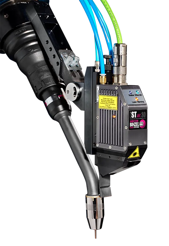
The iSENSE TRACK ARC (iST ARC) line from ABICOR BINZEL is a type of seam tracking sensor that enables you to achieve perfect weld in automated welding. This type of sensor detects deviations at joints from 0.1 mm gap width and adjusts the torch guidance in real time.
When developing this system, the aim was to find a good balance between flexibility and ease of use. Most sensors of this type are either easy to operate but not very flexible. Or others are customized and adapted to the user's requirements but are complicated in operation.
iST ARC sensor setup in the welding process
-
The correct position of an iST ARC sensor is to have the laser line about 25 mm in front of the welding torch (look ahead or preview distance). Shortly before the welding torch reaches the position, the sensor has already detected and measured the joint. The robot controller uses the measurement of the joint position and calculates the position of the seam.
-
In the immediately following step, the robot controller checks how this position corresponds to the programmed path. It then updates its actual path to keep the weld on the joint.
-
The profile of the joint with width, depth and offset is also measured by the sensor software. If necessary, the welding parameters are then adjusted by the robot controller in the same way.
-
The sensor can calculate and transmit updated data for path planning in the robot controller faster than required. This is independent of whether it is an arc welding process or a fast laser welding process.
-
The iST ARC uses the same principle for seam tracking as for seam search. The seam search is used to position the welding torch correctly before the welding process can start.
-
The same applies to short seams, such as tacks, where the position on the component may be different but seam tracking is not required or possible. Optical seam tracking with the iST ARC is faster and more flexible than other methods for determining the welding position before the process starts.
-
A good seam tracking sensor must be able to filter out interfering factors such as the arc, welding spatter and fumes from the process. The iST ARC can filter out almost the entire wavelength spectrum of the process using a special filter. The wavelength of the laser line is optimally detected. It is also resistant to heat, welding spatter and fumes.
-
Different sensor models of the iST ARC ensure that practically the entire range of joint sizes can be covered. They offer a high resolution for very fine joints such as butt welds or a very wide field of view for very wide joints that have to be welded in multiple layers.
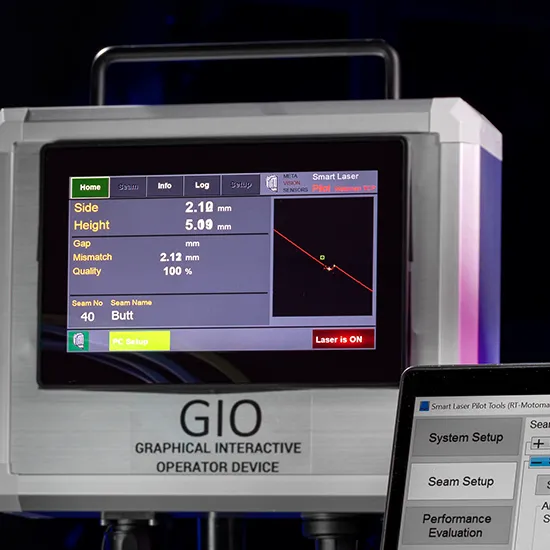
iST ARC user interface
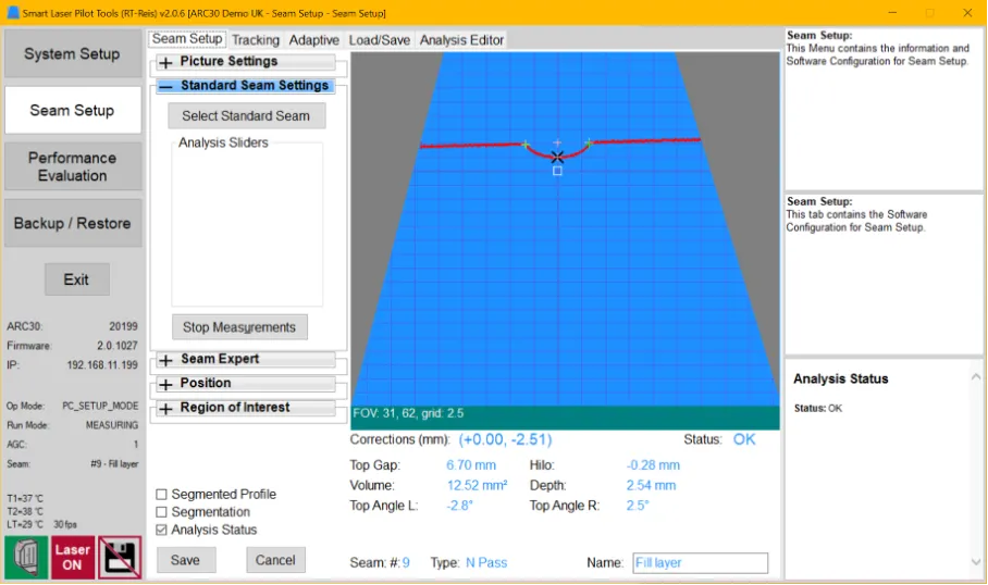
Screen left:
Menus for different top level actions like system setup, seam setup, performance etc.
Screen center:
For each top level menu there are menus with tabs for different groups of settings and expandable menus for each function.
Screen right:
Help area. The top section shows information on the top level menu, the middle section shows the help on the active tab and the functions available. The bottom area displays help for the function that is currently selected with the mouse or the status of the measurement when configuring the measurement.

Example of menus to select standard seam types. The software not only shows the seam name, but also a thumbnail of the seam and, for each seam type, an example of the seam profile that the sensor sees and a description of when this is used.

This example shows a more detailed menu setting that help make the software even more flexible. More detailed help is also displayed (right side, lower box) to explain the different settings.
Laser triangulation sensors such as the iST ARC series from ABICOR BINZEL are among the most widely used sensor types on the market because they cover a wide range of applications and are very user-friendly. Of course, there are many other seam tracking sensors for automated welding. Mainly for very specific applications.
If you have components that place special demands on the sensor and require other specifications, such as a different field of view or a different distance to the workpiece, please get in touch with your contact at ABICOR BINZEL. They will discuss your issue with us and we will take care of your specific request.
When does it become worthwhile to invest in a seam tracking sensor?
In series production, it is difficult to afford to produce incorrectly welded components or to invest huge sums in unnecessarily consumed filler material. Investing in a seam tracking sensor is worthwhile for any automated series production in order to make the joining processes more efficient and economical.
The fact is: Besides the OCT method, laser triangulation is one of the most expensive methods. The acquisition costs for an optical seam tracking sensor can easily be in the low five-figure range. Depending on the production volume, however, these costs are quickly recouped with a higher output of well-welded components and less reworking. Tactile sensors are generally only used for simple, linear seams, as these form an interfering contour compared to optical sensors and must always be in contact with the component. It is therefore not a flexible solution.
We also often find that people are wary of using a seam tracking sensor. Especially when they start into automation. Yes, the technology is different to manual welding. Yes, you need employees who are interested in technology and ideally have experience in robot welding and programming skills.
But the bottom line for you is:
- You reduce rework to a minimum
- You have hardly any rejects
- You need less expensive additional material and shielding gas
- You weld faster while maintaining high quality

Depending on the application, a perfect weld can also mean that you have to feed less filler wire into the joint if the seam tracking sensor works adaptively. Less material means less shielding gas, lower running costs and less weight for each individual component. Depending on where the component is used later, this can make a decisive difference in terms of safety and environmental friendliness.
This project gives an impression of how the investment in a seam tracking sensor pays for itself in the results.
Situation
When welding a safety-critical component for a leading car body manufacturer, many weld seams were not positioned correctly. The production line consisted of 2 x 8 welding robots. One rework station was required per production line to keep up with the level of rework required.
Challenge
The rework stations caused additional production costs. A way was sought to place the weld seams more precisely to reduce rework.
Solution with optical seam tracking
The integration of optical seam tracking sensors on all 16 robots meant that the weld quality was improved, rework decreased and both rework stations were no longer required.
Optical seam tracking in practice

More efficiency required
- Situation & challenge
A renowned manufacturer of propane tanks wanted to make the operation of its welding systems simpler and more efficient. In addition, the rework and reject rate of the welded tanks was too high. The manufactured products were leaking too often.
-
Solution
The automated production lines for the production of larger tanks (> 40 kg) were equipped with a total of 6 seam tracking sensors – for both circumferential and longitudinal welding.
-
Result
Firstly, waste and rework have been drastically reduced. In addition, one less machine operator is now required, who previously always had to align the torch manually.
High tolerances
- Situation & challenge
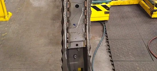
A Tier 1 supplier for the automotive industry welds commercial vehicle ladder frames, among other things. Due to the tolerances in both the position and fit up of the raw parts, it was necessary to use very wide weld seams with a lot of filler material to ensure a secure connection. This resulted in a high cycle time and high consumption of filler material (welding wire). A cost-saving solution was sought.
-
Solution
With the help of a seam tracking sensor, it is now possible to precisely locate and measure the fit up of the welding joint.
-
Result
With precise positioning of the weld seams and measurement of the part fit up, the cycle time has been reduced by around 1/3 and production requires significantly less filler material. This saves on cycle time, welding wire use and also on the weight of the product, as well as savings in gas and energy use.
Complicated welding torch position
- Situation & challenge
A leading manufacturer of solutions for water heating, water supply and water treatment equipment produces water tanks, among other things. As there are both lateral and vertical variations in the seam position, different tank diameters require different weld positions, to maintain the required torch alignment. These issues often led to leaks. The company manufactures 4 hot water tanks of this type with different diameters.
For the welding process, the welding torch is mounted to a set of y/z-axis slides which allows the sensor to keep the torch positioned correctly in the horizontal and vertical axes. These y/z slides are mounted to another set of x-axis slides that automatically adjusts the x-position (welding direction) for different tank diameters to position the weld at the correct position (12 degrees) relative to the top center of the tank.
-
Solution
Once a seam tracking sensor has been implemented, the system control unit now adapts to a different tank diameter. To do this, the operator selects the tank diameter to be welded on the user interface of the sensor system. The x-axis slide assembly then moves so that the y/z slide assembly remains correctly positioned at 12 degrees from top center for that diameter and the sensor system continuously tracks the actual seam position using the y/z axis.
-
Result
The x-axis slide assembly is not controlled directly by the seam tracking sensor, but by pre-programmed movements in the sensor system. This is unique. This solution is now to be introduced in other branches of this company, so they can also benefit from less scrap, less leaks and lower warranty claims.
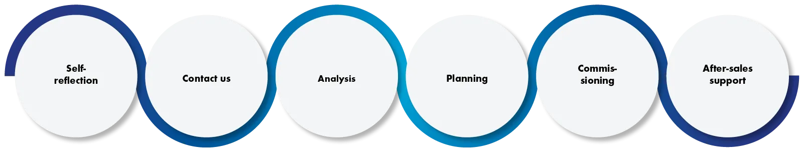
Self-reflection
What is your current situation?
- High scrap rates
- Lot of rework
- Lot of filler material
- Long processing times …
Contact us
Together we will review your situation
Please send an e-mail to: seam-tracking@binzel-abicor.com
Analysis
Together we will check
- Can we track that?
- Does that make sense?
- Can we solve the problem with this?
- Is there trust?
Planning
Together we will coordinate
- As an integrator, you have the know-how about your customer's project. We provide you with answers to open questions.
- As a direct user, you know your processes best. We advise and support you when integrating an optical seam tracking system.
Commissioning
Together we will install
As soon as the planning is complete, we will install the system together with you and set up the seam patterns.
After-sales support
Together we will clarify
- We will clarify any questions, special requirements or problems together with you.
- You can also obtain spare parts from us if required.
Video
Butt joint, lap joint, fillet, multi-layer welding, adaptive welding – with the iST ARC seam tracking sensor from ABICOR BINZEL, every weld seam is placed where it should be during robot welding. See how the welding robot uses the iST ARC seam tracking sensor to automatically compensate for changes in the joint path in real time and create the perfect weld seam.
Sources
DVS leaflet 0927-2: Sensors for fully mechanical and automated arc welding processes – Instructions for use, DVS Technical Committee, Working Group V2 "Arc Welding", Subgroup V2.6 "Mechanization, automation, use of robots in arc welding", November 2021
Editorial team
We hope that you have found valuable information on weld seam tracking for your applications in this e-book – and for your perfect weld.
Your suggestions and comments on this e-book are always welcome.
The following people contributed to this eBook:
Norbert Höppe
Jonathan Moore
Herbert Burbach
Carmen Laux
Christine Rinn
Melissa Haus
Head of Business Unit Laser & Sensor Systems, ABICOR BINZEL LASER SYSTEMS
Technical Specialist, ABICOR BINZEL
Art Director • Global Head of Media & Web Design | Events
Assistant Global Director Marketing
Copywriter • Media & Web Design | Content & Social Media
Marketing Specialist • Media & Web Design | Events
2025 by ABICOR BINZEL
© All rights reserved. This e-book is protected by copyright and may not be reproduced, stored or transmitted in any form or by any means, electronic, mechanical, photocopying, recording or otherwise, without the prior permission of the copyright owner.