Torch Exchange Station TES

Increase productivity & flexibility ...
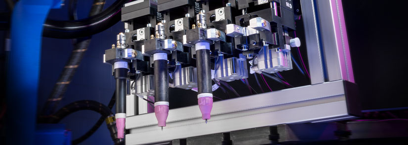
The torch exchange station TES can be used anywhere where welding torches need to be exchanged quickly and reliably. The strengths of the system include a change of torch geometry or even preventive torch changes for servicing wear parts of a TIG welding torch ABITIG® WH or MIG/MAG WH welding torch.
Thanks to the modular system design, up to four TES units can be mated together. The exchange stations are controlled by a PLC or by integrating the TES module into a field bus system. This guarantees full control of the units status at any time. Integrated sensors help record the position of the changing movements and recognize the position of the welding torch for the exchanging process.
The torch exchanging movement is carried out by the welding robot. This allows freedom with respect to designing the welding cell and offers excellent flexibility in positioning the exchange stations in the welding cell – regardless of whether it is on a large gantry welding system in the heavy engineering plant or in compact welding cells in mass production facilities.
In combination with the proven MIG/MAG WH welding torch necks, the integrated cutting of the wire electrodes ensures safe and secure torch exchanges, even if the wire electrode has melted to the contact tip of the welding torch due to poor arc starts, wire feed faults etc.
Arguments that speak for themselves:
- Simple and inexpensive solution for automatic torch exchanges
- Up to four exchange stations can be mated
- Can be used for TIG* and MIG/MAG applications
- Simple and durable design
- Low operating and maintenance costs
- Increased uptime
- Use of different torch geometries for better part accessibility
* currently only without cold wire feed

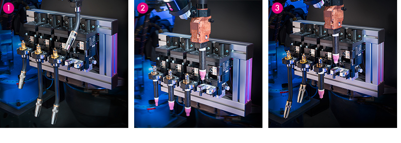
1. Torch exchange station TES with MIG/MAG welding torch WH
2. Torch exchange station TES with TIG welding torches ABITIG® WH
3. Torch exchange station TES with MIG/MAG and ABITIG® WH welding torch
Front system overview
1. Zero position, locking body down with locking fork retracted
2. Locking body up, locking fork extended
3. Locking body up, locking fork retracted
4. Locking body down, locking fork extended
Rear view of pneumatic connections
1. Pneumatic cylinder end position sensors
Technical data
| Operating pressure: | max. 116 psi / min. 87 psi |
| Pneumatic connection: | Connection Ø 6 mm |
| Electrical connection: | Cable connections M12 4 Outputs – Proximity switch 24 V DC / max. 200 mA – Switch output pnp No 2 Outputs – Proximity switch 24 V DC / max. 200 mA – Switch output pnp No 2 Inputs* – 5/2 solenoid valves 24 V DC – Power consumption 2.8 W * depending on the PN |

