Fig. 4Structure and function of the iROB 301 and iROB 401 AControl panel BMain switch CNot assigned DVoltage test lead connection EPower supply connection (welding torch side) FCooling unit (optional) GDriving carriage (optional) HWorkpiece connection INot assigned JMains control LED
Fig. 5iROB 501 structure and function AControl panel BMain switch CNot assigned DVoltage test lead connection EPower supply connection (welding torch side) FCooling unit (optional) GDriving carriage (optional) HWorkpiece connection INot assigned JMains control LED
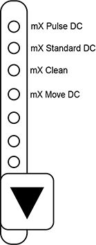
The device is a component of an automatic welding system. The built-in microprocessor facilitates complete control of all welding functions. The device is suitable for the following welding procedures/functions:
mX Standard DC | Standard welding procedures without pulses. From short arc with low energy input to high power spray arc. Suitable for all base materials, cored wires, and shielding gases. |
mX Pulse DC | Pulse welding process for different penetration profiles. Standard and high-performance settings for all base materials, flux cored wires, and shielding gases. |
mX Clean (not available for iROB 301) | Less spatter in the short arc due to modified bead separation. Higher welding speed for large tolerances, flat and uniform seam geometry. |
mX Move DC | Focus on CrNi and Al Controlled heat input by pulsing at two power levels.. TIG-like seam surface. |
Penetration Control | Controlled penetration. High welding speed with reduced risk of undercuts. |
All welding parameters can be saved to the integrated job memory. In synergy mode, the welding voltage is automatically adjusted to the set welding current. The parameter setting function can be used to finely adjust the automatically determined welding voltage. Use of the Penetration Control function makes it possible to automatically adjust the wire feed speed so that the welding current remains constant even if the free welding wire end varies.
The control elements may vary depending on the product type.
BRight digital display C<Parameter setting> knob D<Toggle welding current/wire feed speed> button E<Toggle voltage> button F<Parameter selection> button G<Function> button H<Gas check> button I<Wire feed> button J<Welding speed> selection button K<Welding procedure> selection button L<Shielding gas type> selection button M<Welding wire material> selection button N<Welding wire diameter> selection button O<Operating mode> selection button | P<Tack time> button Q<Arc dynamics> button R<Release start welding/end crater parameter> button S<Penetration control> button T<Move frequency> button U<Cooling unit on/off> button (optional) V<Synergy mode ON/OFF> button W<Weld data capture> button X<Load> button Y<Save> button Z<Enter> button AA<Warning/temperature> LED ABUSB port ACService interface ADIndicator LEDs |
|---|---|
Pos. | Name | Function |
|---|---|---|
A | Left digital display | During welding, the welding current is displayed and the <A> LED illuminates. When making settings, the set value is displayed and the corresponding LED illuminates. |
B | Right digital display | The welding voltage is displayed during welding. When making settings, the set value is displayed and the corresponding LED illuminates. |
C | <Parameter setting> knob
| Adjusts the selected parameter value (welding current, welding voltage, or wire feed speed). |
D | <Toggle welding current/
| Selects the welding current and wire feed speed. The value is displayed in the left digital display and can be adjusted via the parameter setting function. The mode can be switched by pressing the button. |
E | <Toggle voltage> button
| Selects the welding voltage. The value is displayed in the right digital display and can be adjusted via the parameter setting function. If synergy mode has been selected for adjusting the voltage, the displayed value can be switched between the absolute value and the correction value by pressing the button. In synergy mode, the voltage is adjusted according to the welding current. The basis of the characteristic curve value is ± 0. This value is used for fine tuning. |
F | <Parameter selection> button
| Switches between the welding parameters (shielding gas pre-flow time, starting current, main current, end current, and shielding gas post-flow time). During welding, the set value can be displayed on the digital display. |
G | <Function> button
| Selects internal functions. If the button is pressed for 1 second or longer, the LED illuminates and the internal function mode is switched on. |
H | <Shielding gas check> button
| Allows shielding gas to flow. When the button is pressed, the LED illuminates and shielding gas is emitted. After 2 minutes, the shielding gas flow stops automatically. When the button is pressed again, the LED extinguishes and the shielding gas flow stops. |
I | <Wire feed> button
| Feeds the welding wire. When the button is pressed, the LED illuminates and welding wire is fed. The wire feed speed can be adjusted via the <Parameter setting> knob. If an analog remote control is connected, the wire feed speed can be adjusted via the current setting on the analog remote control. |
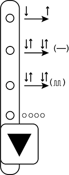
J | <Welding speed> selection button
| Selects the desired welding speed. The selection option depends on the installed options. The LED for the selected welding speed illuminates. Some combinations of welding wire diameter, welding wire material, shielding gas type, and welding procedure are not sensible. If an impermissible combination is selected, the LED flashes. |
K | <Welding procedure> selection button
| Selects the desired welding procedure. The selection option depends on the installed options. The LED for the selected welding procedure illuminates. Some combinations of welding wire diameter, welding wire material, welding speed, and shielding gas type are not sensible. If an impermissible combination is selected, the LED flashes. |
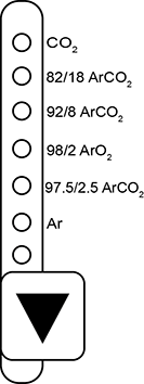
L | <Shielding gas type> selection button
| Selects the desired shielding gas type. The selection option depends on the installed options. The LED for the selected shielding gas type illuminates. Some combinations of welding wire diameter, welding wire material, welding speed, and welding procedure are not sensible. If an impermissible combination is selected, the LED flashes. |
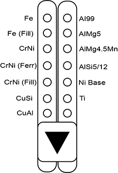
M | <Welding wire material> selection button
| Selects the desired welding wire material. The selection option depends on the installed options. The LED for the selected welding wire material illuminates. Some combinations of welding wire diameter, welding speed, shielding gas type, and welding procedure are not sensible. If an impermissible combination is selected, the LED flashes. |
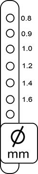
N | <Welding wire diameter> selection button
| Selects the desired welding wire diameter. The selection option depends on the installed options. The LED for the selected welding wire diameter illuminates. Some combinations of welding wire material, welding speed, shielding gas type, and welding procedure are not sensible. If an impermissible combination is selected, the LED flashes. |
O | <Operating mode> selection button
| No function. |
P | <Time> button
| No function. |
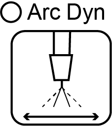
Q | <Arc dynamics> button
| Switches the arc characteristic from soft (+10) to hard (−10). When the button is pressed, the LED illuminates and the <Parameter setting> knob can be used to adjust the parameters. The current characteristic is shown in the right digital display. |
R | <Release start welding/end crater parameter> button
| Enables the activation of start welding/end crater parameters when the "two-step" operating mode is selected in automatic mode (internal functions F45–47). When the button is pressed, the LED illuminates and the activation of start welding/end crater parameters is enabled. |
S | <Penetration control> button
| Activate the Penetration Control function The wire feed speed automatically adjusts so that the welding current remains constant even if the free welding wire end varies. This function is available when "steel", "steel flux-cored wire", "stainless steel" or "stainless steel flux-cored wire" is selected. LED on: penetration control switched on. LED off: penetration control switched off. |
T | <Move frequency> button
| Defines the double pulse frequency if mX Move DC welding procedure is selected. When the button is pressed, the LED illuminates and the <Parameter setting> knob can be used to adjust the frequency. |
U | <Cooling unit on/off> button
| Switches the optional cooling unit on or off. The unit is switched on/off when the button is pressed for 3 seconds. LED on: cooling unit is switched on. LED off: cooling unit is switched off. |
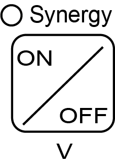
V | <Synergy mode ON/OFF> button
| Defines the welding voltage. LED on: LED off: Synergy mode OFF: power and voltage are set independent of each other. |
W | <Weld data capture> button
| No function. |
X | <Load> button
| Loads the welding parameters stored in the job memory. Creates a data backup on a USB storage device. |
Y | <Save> button
| Saves the set parameters in the job memory. Imports a data backup from a USB storage device. |
Z | <Enter> button
| Performs the administrative functions such as button lock, password, and assignment of welding parameters to memory locations. If the button is pressed for 3 seconds or more, button lock is activated. |
AA | LED warning/temperature
| The LED illuminates or blinks as soon as an error occurs or if the device overheats. |
AB | USB port | Data can be read from or stored to a USB storage device via the port. |
AC | Input for service | The interface is used exclusively for service purposes. |


The LEDs on the control panel have the following meanings:
BLED for temperature CLED for amperes DLED for wire feed speed ELED for time FLED for pulse frequency GLED for volts HLED for arc length and/or voltage correction | ILED ratio of upper/lower value of wire feed speed with mX Move DC JJob No. LED KLED shielding gas post-flow LLED for end crater filling parameter MLED for main welding parameter NLED for start welding parameter OLED shielding gas pre-flow |
|---|---|
WiFi router and control app (optional)
AWiFi router | |
|---|---|
If the device is equipped with an optional WiFi router, all device functions can also be controlled and programmed via the optional iROB POWER App control app.
Ambient temperature | −20°C to +55°C |
Relative humidity | 20% to 80% (non-condensing) |
1.According to EN IEC 60974-1
Ambient temperature | −10°C to +40°C |
Relative humidity | 20% to 80% (non-condensing) |
Max. tilt angle | 10° |
1.According to EN IEC 60974-1
iROB 301 | iROB 401 | iROB 401 | |
|---|---|---|---|
Mains voltage | 400 V ±15% | ||
Number of phases | 3 phases | ||
Rated frequency | 50/60 Hz | ||
Max. current consumption | 21.8 A | 29 A | 36 A |
Max. power consumption | 15.2 kVA, 13.5 kW | 20.1 kVA, 18.1 kW | 25 kVA, |
Fuse on mains side | 32 A; slow-blow | ||
Welding current range | 30 A to 320 A | 30 A to 400 A | 30 A to 500 A |
Working voltage | 15.5 V to 30.0 V | 15.5 V to 34.0 V | 15.5 V to 39.0 V |
Efficiency | 85.5 % | 82.6 % | 83.5 % |
Idle power consumption | 44.0 W | 44.0 W | 44.0 W |
Idle voltage | 80 V maximum | 80 V maximum | 80 V maximum |
Duty cycle 100% (+40°C) | 280 A/28.2 V pulse | 370 A/32.5 V pulse | 410 A/34.5 V pulse |
Duty cycle 60% (+40°C) | 320 A/30.0 V pulse | 380 A/33.0 V DC | 500 A/39.0 V DC |
Duty cycle 50% (+40°C) | — | 400 A/34.0 V DC | — |
Protection type | IP 23 | ||
Welding torch cooling type | Air-cooled | ||
Total weight with cooling unit | 93 kg (cooling unit 31 kg) | 93 kg (cooling unit 31 kg) | 114 kg (cooling unit 31 kg) |
Weight without cooling unit | 62 kg | 62 kg | 83 kg |
Dimensions (L × W × H) | 395 mm × 710 mm × 592 mm | 395 mm × 710 mm × 592 mm | 395 mm × 710 mm × |
Dimensions (L × W × H) of the entire device with cooling unit | 395 mm × 710 mm × | 395 mm × 710 mm × | 395 mm × 710 mm × 1158 mm |
A duty cycle of 60% means that the device rests for 4 minutes after 6 minutes of welding with the specified current.
AData cable for WLAN module (optional) BFieldbus interface (e.g. Ethernet IP) CPower supply for WLAN module (optional) | DWelding torch control lead connection EMPP control lead connection |
|---|---|